CINEVERSITY

  • RE: Objects position and rotation

    Thanks a lot, purchase-interaction, for the file. So much more information.

    The whole model was slightly titled. You can see that in the right or left view.

    So I used the Parent to get it back to a leveled orientation (R.P. -0.3645º)

    With that being done, I selected all but the Parent and used the Axis Tool, as shown in the image.

    This left me with another problem, as the Parent had a tilted Axis but leveled polygons)

    So I called up a new Null, selected all children of the previous group (Parent null not selected), dragged all under the new Null, copied and pasted the name to the new Null, and deleted the old Null.

    There are other ideas to do that, but with this amount of elements, I prefer this method.

    Your file
    https://stcineversityprod02.blob.core.windows.net/$web/Cineversity_Forum_Support/2023_PROJECTS_DRS/20230925_CV4_2024_drs_23_MOao_01.c4d.zip

    Screen Shot 2023-09-25 at 1.59.44 PM.jpg

    All the best

    posted in Question & Answers
  • RE: Length of a helix

    You're very welcome, AlexC.

    My best wishes for the project.

    posted in Question & Answers
  • RE: Length of a helix

    Thanks for the file, AlexC!

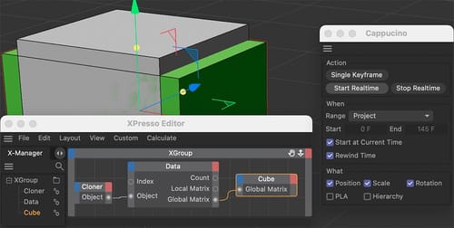
    I typically use an XPresso Tag for this. In the example, I have fed the length of the Spline into the Object's name so you can see in the Object Manager what is going on. (I deleted anything else in the file to be able to post it here directly.)

    CV4_2024_drs_23_XPsl_01.c4d

    All the best

    posted in Question & Answers
  • RE: Object 'spinning' in a bowl/globe

    Thanks, difference-front.

    Please have a look here:
    CV4_2024_drs_23_TPdt_03.c4d

    I use a Spline as shape and fine-tune the position then with the Inheritance Effector.

    All the best

    posted in Question & Answers
  • RE: Objects position and rotation

    Hi Purchase-interaction,

    Images do not tell me a lot. What you see in the images is not what I see. For me, it looks OK, as I have no idea what it should look like.

    With images, I'm left to interpret what I see and start guessing. I understand that you don't like sharing the project file with 1400 objects here.

    Suggestion 1
    If you like to rotate the whole object, place all of them under a Null Parent, then rotate that Null.

    Suggestion 2
    Use the Freeze options if you like to have all objects as they are, and no visible change, but all rotations are set to zero. Select all and use the Attributes Manager> Coordinates> Freeze Transformation> Freeze All.

    I hope the two guesses will help; otherwise, to share more, Perhaps create a tiny example file and share more details. I'm happy to look into it.

    All the best

    posted in Question & Answers
  • RE: macros/actions recording in C4D ?

    You're very welcome, kolodzick!

    posted in Question & Answers
  • RE: Object 'spinning' in a bowl/globe

    Hi difference-front,

    Please have a look here:

    CV4_2024_drs_23_TPdt_02.c4d

    I have used mostly Thinking Particles here, as it feels the better way to adjust when and how things move. In the Xpresso Tag, I have marked the nodes that will change the outcome with a bright green Title Color.
    One requirement, Project Duration, and Particle Life must match.

    =======

    It is not needed for the solution above, but since you asked, typically, you can introduce more energy into the "clones" when the bounce is above 100%. To reduce it needs to reduce that energy. Did you use the Bullet or Simulation system?
    When clones escape, the calculation needs a higher "step" setting.

    Images higher than 500 pixels will not work.

    All the best

    posted in Question & Answers
  • RE: Open Edges and Printing Prep

    Thanks for the feedback, MFVis,

    Well, that is pretty much why I started with the Volume Workflow.

    The Remesh Object is perhaps one of the most helpful functions here, but even this option has no idea which one of the polygons to take here.

    There are limitations, as one might want to keep the polygon while the next artist the other polygon. It is not that simple. If anyone has an idea, submit it to MAXON.

    Have a great weekend.

    posted in Question & Answers
  • RE: Open Edges and Printing Prep

    Hi MFVis,

    Yes, that would be great, a function that knows which one to delete.
    The polygons inside the mesh are not double polygons; they are somewhere, and finding which one to keep is not easy for an algorithm.

    So, the first test for me is typically the Modeling Check; do it on a copy while hiding the original. It lets you see what the whole thing is about and lets you select the parts that will not work.
    If you delete them, you might delete too much, but if you do it with a copy, it helps to understand the problem.

    Next is a simple one: place the object under a Subdivision Surface. It shows often where things went wrong.

    With that knowledge, some polygons can be picked out pulled on to see if they are connected, etc. CMD-Z brings it back, then uses the selected and Selection> Hide Selected. With this, more can be seen inside of the object.

    Now comes the hard part: repair or start over.

    The answer was easy in this case: start over, but use a few polygons to be fast with it.

    The front frame selected (visible only), Invert [U~I], then delete all others.
    The remainder selected and Extrude with Create Caps on.
    The offset can be measured from the original part.
    Now: Create Caps OFF! This is often forgotten and creates models like the problem model we discuss. So, always OFF after an operation.

    Then offset some of the other parts (Symmetry selection can help here)

    The lower part of the frame has a titled area, which can be easily moved with the related points. Extrude the small side as in the original. Done.

    Check with SDS to see how that should have looked to gain an idea for future tasks.

    All the best

    posted in Question & Answers
  • RE: Open Edges and Printing Prep

    Thanks for the reply, MFVis,

    Yes, Volume needs some exploration to find a good balance. The Mesher set to Adaptive between 0.5 and 5% (I used 3% in the example above) will help to keep things reasonable.

    Open Edge Question: Upload only the "Window Casing Master" frame. You already have a clue. Exploration – Just take the vertical side polygon of it and pull it in one or the other direction. There is a lot of overlap of edges and geometry.

    Here is my take on the frame, which was tested in Shapeways and found to be OK. The file you shared had 119 polygons; my version has 82. Can you see a difference? They look the same, but a huge difference in Polygons.
    CV4_2024_drs_23_MOcm_01.c4d

    Screen Shot 2023-09-22 at 1.55.49 PM.jpg

    All the best

    posted in Question & Answers