You're very welcome, kana!
Enjoy!
I do Film - Photography, and everything 3D/4D. (RED/Cinema 4D)
I’m “fluent” in camera work, practical (film and still), and virtual.
My experience includes long immersion in Film, Photography, Architecture, and Motion Design.
Switching between the C4D camera and my RED-Epic-Dragon is effortless for me.
Film: everything from the idea to the festivals&awards; First Feature Film Award in 1994. Since then many more awards.
I studied Art (MFA), Set-design, Film/Video, and Architecture and did my Ph.D. in Computer Animation.
I have six degrees, three of them advanced, but I never stopped learning. In the past 28 years, I have updated my knowledge constantly with training all along the feature film Pipeline (including VFX/Color).
Member of Visual Effects Society, Digital Cinematography Society
Alumina of the Hollywood Color Academy for professional Colorist
I have mentored Artists since 2004, with an emphasis on Cinema 4D.
Senior Trainer, Maxon Master Trainer, L&D - Strategy. MFA.
You're very welcome, kana!
Enjoy!
Dear Friends,
Some of you have followed my journey since I joined Cineversity on May 4, 2006, while others might remember me even further back from my years teaching Cinema 4D with Pixelcorps (PXC). Since 2004, along with four different versions of our forums here, plus the one from the Pixelcorps, I have had the privilege of answering around 30,000 questions. Whether through project files, images, or those quick one-minute screen captures, being there for you has been my constant.
I still vividly remember being a demo artist at NAB in 2006 when MoGraph was first premiered; sharing over a hundred videos shortly after to help everyone get started remains one of my favorite milestones.
CV1 where is all started with Cineversity in 2006! Sometimes with 30 questions a day.

A lot has happened since those early days, but one thing has always been crystal clear: your creativity is boundless. I am so proud of the work you’ve done and the trust you placed in me—especially those of you who reached out with questions that felt difficult or uncomfortable to ask. I took that trust seriously and learned from every single one of those interactions. Your needs and your curiosity taught me more about this industry and our tools than I could have ever learned through any other source.
I have truly enjoyed being here for you pretty much 24/7, through holidays and vacations alike, because I love what I do. As things often do, life is changing. Structural changes allow me to face new challenges, and I hope I can grow into those. Those changes also require me, after 22 years of answering in various forums, to stop – for now. Something that pains me, and I feel the loss.
I want to say a sincere thank you to every artist I’ve had the joy of interacting with here. You are all wonderful, and I hope you never stop exploring. I certainly won’t. While it isn't clear yet where or how I will continue, my hope is to find a new place to support the artist community at one point again, as that has become such an essential part of my life. Thank you for making Cineversity such a great experience: 2006-2026. Thank you. I surely will miss you all.
Please treat my dear friend with the same care you have shown over the decades, as I hand over this precious forum. Thanks for your professionalism and trust over the decades.
Keep creating!
Dr. Sassi
Hi kana,
Thank you again for your file
Thank you as well, for your kind feedback.
Yes and no. Yes, when the spheres do not interact with each other, no, when they need to interact as well with each other.
The key is the Simulation Scene. The default one is always in the Attribute Manager> Mode> Scene> Simulations, and more can be called up in the Main Menu> Scene.
There is no direct interaction between two Simulation Scenes, or among many. Here is the No of my reply grounded.
More about:
https://help.maxon.net/c4d/2026/en-us/Default.htm#html/OPBDSCENE.html
Please note that is sadly my last reply in this forum, I will not be able to answer more. I hope a good friend of mine will take over.
My best wishes with your project
You're very welcome, MaverickMongoose,
Thanks for the feedback!
My best wishes for your project
Hi kana,
Here is the file discussed above:
CV4_2026_drs_26_PAbr_01.c4d
Please let me know if anything is not clear. I'm happy to look into it.
Sorry about that mix up. The file was wrong, you are correct.
Cheers
Hi kana,
Please have a look here:
CV4_2026_drs_26_PAbr_01.c4d
I have used the Particles for the Simulation, and left MoGraph clones for the visuals only.
For that, the Particles needed a larger radius.
The Specific Particle Collider object can be used group-wise.
That means when a Particle can be moved from a Collider Group to a non-Collider group, then we have the first step for the effect you are after.
The switch here is based on the Field, but it could be done with the Plane, but it would need more points, or it would get less precise.
Since the Particles switches groups, the problem is now that the Cloner can use only one Group.
To remedy this, the Multi Group option is used, which can contain more than one group.
I made the sphere larger and overlapped the Emitter to showcase it better.
I hope that helps
Cheers
Hi medium-share,
Apply all materials in the Source project file, then sort it in the XRef manager in the Host Project.
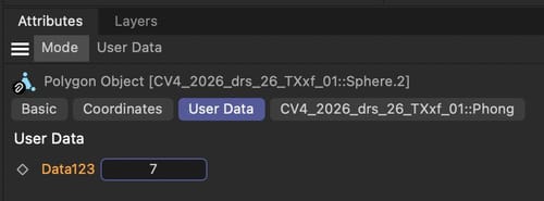
An alternative would be to add a User Data (integer) to the Object and read this in the attached RS Material via User Data (Integer) node out, and use it as a switch inside the Materials.
The User Data stays active while used in XRef in 2026, just explored it.
Example, open this via XRef, User Data is on the object.
CV4_2026_drs_26_TXxf_01.c4d

Render.
Perhaps having no materials in the Source file might not work for your process, and similarly, the idea to just adding a Material on the right side, which has limitations.
You could also make an input via "Share Your Idea".
https://www.maxon.net/en/
Cheers
Hi Simon,
This is a general question. If they are the same, what would be the reason to copy those?
In short, Points are the basic for Polygons. Points are related to the object axis.
Tools to copy are, of course, Cmd-C and then CMD-V, while the copy needs the source object to be active, and for CMD-V the receiving object.
In the moment the Polygons are pasted, they are not connected. If they fit, then the Mesh> Remove> Optimize is the option to turn point siting on or very close to each other into one point. Which means the mesh is connected. Using a Subdivision Surface parent for a moment, often, if the operation was successful.
The Weld function can help in single pairing options.
Sharing a C4D is more helpful to answer, as I can see more detailed what is needed.
Cheers
Hi Fab,
Please have a look here:
CV4_2026_drs_26_PAfs_01.c4d

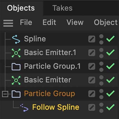
The Follow Spline needs to sit as a child under the group you like to affect only.
Let me know if that works for you.
Cheers
Thanks for the reply, MaverickMongoose.
Yes, it can be sometimes tricky; here I have the MoGraph Effectors as Deformers in Object mode in mind. I have never tried to bake the results. So I needed to have a closer look today.
XPresso can see a change of point values, which would indicate that the Effector uses the axis to Position, rotate, or Scale the object. Selecting the object shows the Axis static, even though the cube moves.
Since the points, even in the structure Manger are static, my unofficial conclusion is that the Effector in Deformer Object mode takes over from the axis it gets and acts on its own, like an object clone.
As you surely know, points are related to the object axis. So if the points and the object axis don't change, but the visual, (again) something takes over.
Which made me look at the points, via Tracer, then with a Cloner in object mode, etc. (and etc is a longer list of objects I tried). All works visually, but not baking.
Hence, the longer calculation chain. I harvest the point data with a MoGraph Matrix object, then apply that data to an object in Point mode. PLA baking is now possible.
Example
CV4_2026_drs_26_MGod_01.c4d
The other way might be already too similar, using a polygon that is "deformed via Effector, then the Polygon Object is used in a Cloner. Which, of course, made me ask, why not direct in the Cloner? Pure interest would be my excuse.
Example
CV4_2026_drs_26_MGpp_01.c4d
Enjoy