Banding/Stripes in the Render
-
Wir arbeiten mit der Version 2024.4.0
Wir erstellen Modelle, die mindestens ein Druckteil haben.
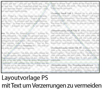
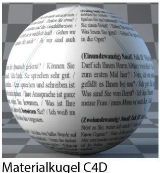
In diesem speziellen Fall sind es vier Druckteile und hier ist es besonders wichtig, das diese genau und maßhaltig sitzen.(Dazu wird eine Layoutvorlage, im AI erstellt, in PS eingeladen, als tiff gespeichert und dieses tiff im C4 auf die Materialkugel projiziert)
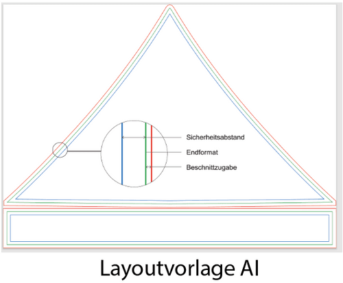
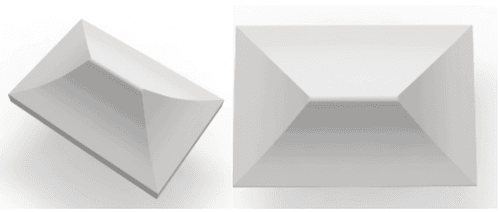
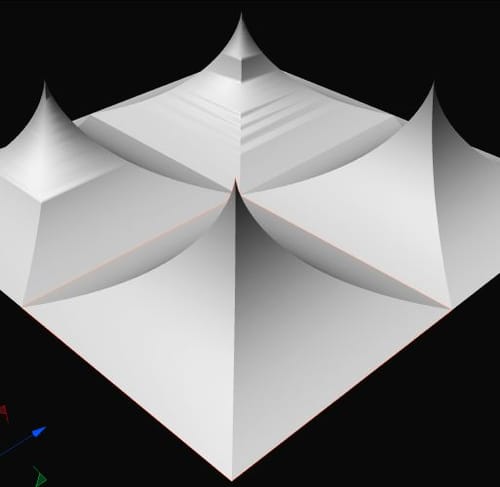
Im vorliegenden Projekt soll ein Zeltdach aus 4 separaten Segmenten entstehen.
Alle 4 Druckteile müssen dafür in einer bestimmten Weise gebogen werden, sollen sich oben an der Zeltspitze wieder punktgenau treffen und das Layout darf sich dabei nicht verziehen.Phase 1:
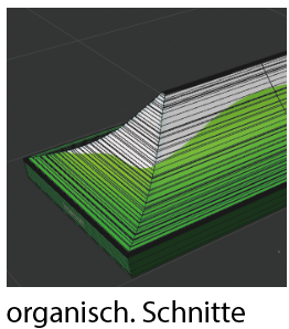
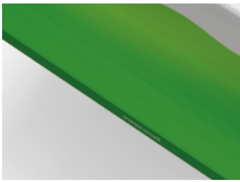
Mit den organischen Schnitten, bekommen wir beim Rendern mit dem Standart-Renderer eine unschöne Streifenbildung. Die Anmutung des Daches wirkt wie viele kleine Linien.
Phase2:
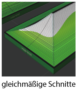
Nach dem Optimieren der Schnitte, geht die Streifenbildung leicht zurück.
Trotz gleichmäßiger Verteilung der Schnitte, kommt es immer noch zu groben Stufen im Druckteil
Wie können wir hier weiter optimieren?
-
Hi example-market,
Please have a look here while moving the time slider. I have produced two objects with problems and two that should work.
The ones with problems have the Phong Angle animated to see the influence. It is based on 2024.
CV4_2024_drs_25_MOpp_01.c4d
For 2025 version users:
CV4_2025_drs_25_MOpp_01.c4dIs that the problem you have, I don't know. Images don't tell me a lot; I need an example file. Files below 1MB can be attached here as c4d directly. In larger files, please (and only) via DropBox, Wetransfer, Google, Adobe, or Apple cloud services; please, no zip or rar files, no Tiny URLs, etc.
Please paste the URL into the text as is. Sorry for all of that, but security is needed to keep it safe for everyone.So, if the Phong Angle is not solving the problem, please share a simple example file that shows that problem; thank you. I'm happy to look into it.
I have another favor: this is an English-based forum; would you mind using this as a default for your posts as well? Thank you.
My best wishes for your project
-
Hi Dr. Sassi,
Thank you for your reply.
For a first contact we wanted to make sure that we describe the problem correctly and that there are no errors in the problem description due to a translation.
Your example file reflects the issue very well. The reduction of the stripes in the example is impressive. It seems to be a combination of the position of the cuts and the phong. We have already tried the phong, but it does not change the appearance.
We can provide a file. There are three steps included to show the beginning of the project, an intermediate step and the result.We are grateful for any helpful tips.
Kind regards. -
Hi design-sport,
Thanks for the file.
Geometry has some very long polygons, which might work but is not ideal.
A smooth surface requires that the direction of a Polygon Face is calculated (the result is Normal) and, in combination with its neighbor, evaluated.
https://help.maxon.net/c4d/2025/de-de/Default.htm#html/TPHONG.html
Perhaps it is clear, but let me share it to be complete: Edges on Polygons are always straight, never bent.
A facetted object can be a smooth surface while also allowing sharp edges if needed, there is a threshold when one or the other shows up.
This can be difficult, and to get sharp edges even if the rest is "smoothest", the option to Break the phong shading for that edge is optional.
https://help.maxon.net/c4d/2025/de-de/Default.htm#html/5680.htm
Separating the model into four parts does the same to the edges, as they no longer have a neighbor connected to them.
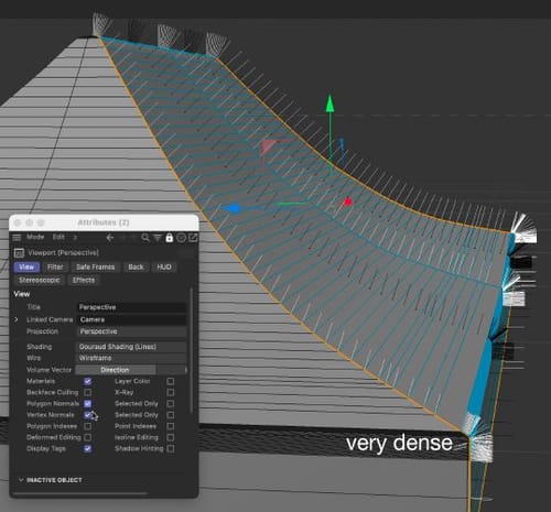
When you look at the image, there are little "pins" (Attribute Manager> Mode> View Settings); the smooth surface is calculated between the pins that are in the middle of the Polygons. It is easy to imagine (so I hope) that the closer the pins are as neighbors (tiny distances), the more rounding needs to be done in a short distance. This means that smoothness has a longer path to unfold if they are at a greater distance from each other.
For a while now, the " Style " option can be selected. In other words, the way the smoothness is calculated and applied.
https://help.maxon.net/c4d/2025/de-de/Default.htm#html/TPHONG-ID_TAGPROPERTIES.html#PHONGTAG_STYLE
While selecting different styles, the Normals of the Points might change, which indicates a different result of the calculation.Here is an example, not optimized in UV for your use, but just to explore if you see problems with it.
CV4_2025_drs_25_MOdc_01.c4dI hope that helps.
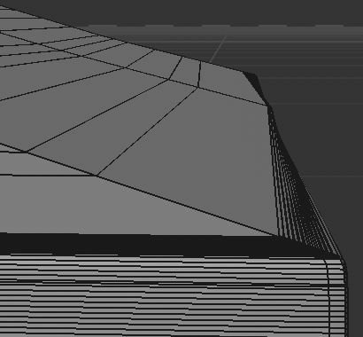
I also found that there is a huge density of polygons in the lower part of the model.
As well some non-parallel polygons, is that on purpose?
As a side note, I'm unclear if you want the projection to look orthogonal to each side or just along the surface.
Enjoy
-
Hi Dr. Sassi,
thank you very much for your valuable tips and the wonderful explanation of the polygon alignment and the resulting effect of the Phong.
We will start another series of tests to determine the optimum number of cuts for different tent sizes. We test how close the cuts should be so that the roof surface appears line-free due to the Phong and yet the edge between the roof segments looks smooth and not angular. We will also look at the roof peak and the transition to the vertical to see how many cuts are actually necessary. The tip on the verticals will help to keep an better overview of the parallels.
We hope to find a good solution. Best regards.
-
Thank you very much, design-sport, for the reply.
I wish you and the team a lot of fun exploring it, with the feeling of having a great outcome based on it.
Cheers