Align an object to the normals of another object's components?
-
Hi there. This is probably a super basic question, and I'm not even sure if I'm framing it properly, but I have an object with some polygons aimed at an arbitrary axis. I have another object that I want to align/orient perpendicular to those polygons, but I'm not sure how to do that.
Let's say I want to put a bolt head on an arbitrary point on an overall spherical shape: how would I ensure that the bolt head is perpendicular to the normal direction of the point (or poly) on which I wish to place it? Thank you!
-
Hi Balakay612,
Perhaps this Quick Tip helps?
https://youtu.be/SV11dJTQeqgPlease let me know if you have something else in mind.
Cheers
-
Yeah, that's just about it -- it's close enough to help me accomplish what I'm trying to do, so thank you! More specifically though, let's say there are four polys that share a central point: those polys all have slightly different normals because of how they were created as part of a sphere. Is there any way to get, say, the average of the polys' normal to use as the placement orientation? What I had to do was cut the polys, paste them back, flatten their scale on the local z axis to effectively give myself the averaged normal, then place the cylinder, then paste back the original polys and weld them back as part of the original sphere. That works, but if there's a better way accomplish that goal, I'm all ears! Thanks for the response!
-
Thanks for teh reply, Balakay612,
A little bit more complex, but also precise for your needs, The calculation of the Normal to a Matrix.
The Constant Node defines the "Up-Vector"
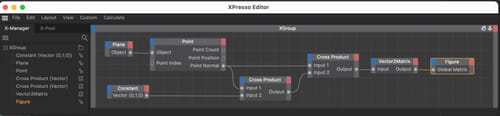
In short and simple:
The First Cross product used the Up Vector and the Normal (of the selected Point in the point node; ID) to create the first cross product, which is then used again with the Normal to get the direction aligned with the normal.Since the Normal is just a direction, you will see that the Object rotates. Once you find the Matrix for the Object, switch off the XPresso.
Cheers
-
I'm going to have to take a closer look at that! I am terrible with math, but I love learning how to use it for stuff like this, so I'm going to study that project file you attached. Thank you!
-
Hi Balakay612,
Thanks for the feedback.
Here is a less precise but much easier way. You might find the Range Mapper tuned accordingly. This means, set a start point of the radius and end point while defing the amount of start and end step.
To fine-tune it, adjust the Spline Curve of the Rangemapper.An example is here:
CV4_2025_dr_25_XPsc_11.c4d
.About the file from the earlier post:
I used the Formula Node here, as it allows me to keep things compact.
This could be done with single Math Nodes, which might make it easier to read.I needed to know the circumference of your reference setup, which would be the 360º of the 3668 radius (Radius 2 PI = Circumference)
With that, I was able to define step length using the 21º you have set up and the step count. ((Circumference*21º)/360º))/ Step-count = Length of a Single step or stair element.
Now, I needed to place that into a formula to have a different Radius driving the number of steps needed to fill the 0º to 21º you have as your fixed boundary.
I hope that helps untangle the XPresso a little bit.
Yes, sometimes Math comes in handy.
Enjoy