Particle Swoosh Controlling
-
Hi there,
I have a question regarding a particle setup with a "follow spline object " and a tracer.
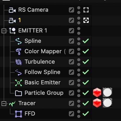
So I created a setup where I have a simple spline, an emitter, a tracer, a follow spline object and a turbulence.
Now I want to controll the start and endpoint size of the emittet particles so the"tubes" are always the same size at start and end.I have different visuals which are presented in a row, so the same height/position woulb be crucial for a seamless transition between them.
Between the start and end point I would like to have variation in the different pictures, so I played with all the follow spline settings and turbulence. Setting the Emitter size really low helps of course, then I need the turbulence to break it up and spread it out. This results in the end point completly different than the start.
Do you have an idea and could point me in a direction where to look closer?
Thanks a ton!
The scene file is here
https://www.dropbox.com/t/GXcl6CYcYZWblOBr
https://ibb.co/RGy60F3M
https://ibb.co/2TFwgMp
-
Hi table-state,
Thank you for the project file and for using Dropbox.
Please have a look here:
CV4_2025_drs_25_MGwv_01.c4d
The speheres are a little bit parger, to see the effect, adjust those to your liking.
I have not used Particles. I hope I've covered your idea in the file.What I understood so far. The start and end points should be the same, while the wave needs to be adjustable, mostly in the center, and then lead to the start and end points matching.
I have marked (Layer chip color) the objects that require the main adjustment. The MoSpline drives the main animation.
If you animate the Noise shader in the Displacer, you can get some extra motion.
Please let me know if you have any questions; I'm happy to look into it.
Please share content here with Dropbox, Google, Adobe, Apple, or WeTransfer. No HTML wrapper, just the plain URL (full, no zip/rare during upload, or tiny URLs). Thank you. It is based on security.
Having your scene file provides me with great support.
Direct upload here: .c4d files, max 1MB; images, max 500px height.All the best
-
Hi Dr. Sassi,
thank you so much for looking into this and providing so much useful information!
Unfortunately, I was not able to get the desired result with your setup. I played with all the settings you mentioned, but couldn't get it quite right.
The problem is, I have some visuals which all have different objects in it. I need to draw the spline manually across the images to get the right interactions with the objects.
Also, I need to control the radius of the splines where there are corners and bendings.Using the particles' setup, I have the most organic looking streams and curves, which I would love to have.
I also found a workaround with an N-Side that runs along the drawn spline and variates in size, while being traced.
It's okayish, but also not so organic as desired.Then I remembered the modifiers for the particle system and played with the flock modifier.
And there it is. I can start with a 1cm emitter radius and then use the flock system to push them apart and also bring them together at the end.Could have done this sooner, and I'm sorry for the time you invested.
Thanks again for all your help, very appreciated as always!
Have a nice weekend!
All the best -
Okay, looks like I was too optimistic. Still can‘t get the end radius/thickness to match the start.
-
Hi table-state,
I need a storyboard to better understand your target with indicators, where and how the images move, and how your ideas of size apply. I'm not clear after your second post what you really want.
I can't help but feel that you can visualize the whole setup in your mind, but the text doesn't define it for me.
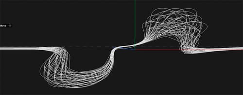
Here is a wild guess, how about an FFD for the Tracer
CV4_2025_drs_25_MGwv_11.c4d
Have a great weekend.Cheers
-
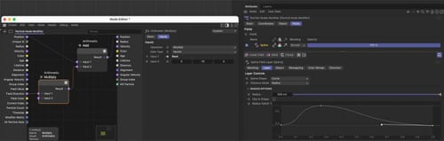
P.S.: how about this?
Using the main Spline as a Field and pulling particles toward it if they move too far out?
The key parameters are the Radius and the Spline field, as well as the parameter of the Multiply Node.
-
Hi Dr. Sassi,
I'm really sorry for the late reply and the sparse information I initially provided.
"I can't help but feel that you can visualize the whole setup in your mind, but the text doesn't define it for me."
After working on this for hours, I forgot that, of course, others have no idea what my thoughts are. : D Very, sorry.
I’ve saved the scene with an example image of a building similar to the ones being used and an example of how they are gonna be displayed later
https://www.dropbox.com/t/6whFCIoX9rSdGgNB
I hope this makes things a bit clearer.
I set the spline to show how I would like to interact with the building—growing and shrinking in size while changing directions. The "swoosh/lines" need to be exactly the same size at the start and end, as the images will be displayed very close to each other on websites... So there needs to be a seamless transition between the pictures.
Thank you for your new input, I`ll have a look right now and get back to you!
All the best -
Forgot to mention: the file contains both of my setups – the one using N-Sides and the one using the particle system, with the latter being my preferred setup. The first one with the N-Sides is my backup solution. It would be acceptable, but I’m not completely satisfied with the smoothness of the swooshes compared to the particle-based version.
-
Hi table-state,
No need to apologize. Your files allowed me to spot the problem.
I can see that the images are shot from a different position, and the particles move in Space. However, you have only one camera in the scene.
Since each image of the building requires a specific camera to represent its original Point of view/Point of interest, as well as focal length, using just one camera will not get you there.
At the moment, you have the two cameras defined; based on each image, the particle results will match. Of course, if the particles are somewhere in Space, it will not work; they need to sit between the cameras and the virtual image plane.
Take both images you like to use, not cropped, and calibrate each image. Calibrating the lens (the focal length, at least) and creating a Lens distortion might not be the deciding key in this case.
Since I have had no full sources here, I can't exactly tell what the lens is, given a 36mm sensor, had a ~38 or ~42 mm lens. I got from one a distortion (tilt), so I assume I don't have the images to work with. But they are both not matching one position.
From my point of view, setting up particles somewhere in Space while using only one camera for two slightly different image perspectives will never match; even if you get it close by massaging the particles, there will be a feeling of mismatch, and I assume that is the point of your question, in essence.
https://help.maxon.net/c4d/2025/en-us/Default.htm#html/TCAMERAMAPPING.html
All the best
-
Hi Dr. Sassi,
Thanks again for reaching out and sharing your thoughts.
I’m not quite sure if I was able to clearly communicate my intentions and goal. It all seems a lot more complex than I initially thought.
I believe there’s no need for camera mapping — the only things that really matter are the same size/radius and position at the start and end. Nothing more.
In the main file, I have 8 cameras with different images. I only uploaded one example since I assumed the specific image wasn’t relevant. The spline is duplicated for each setup, so the start and end points are always the same across all versions.With the traced N-Side setup, this works perfectly — I can simply keyframe the size of the N-Side and match it at the end on the right. But as mentioned, it’s just not as smooth as the particle-based version.
So I guess that’s the deal: I have a working and okay-ish solution, but I’d really love to have the same level of control with the particle setup that I currently have with the N-Side.
To help visualize what I mean... That's all, just the same size at the start and end, as in this screenshot.
https://imgur.com/a/fsGjmGo
or here in dropbox
https://www.dropbox.com/t/kWFPcCW1OY134bBQ
Thanks again, and sorry for the troubles!
-
Hi table-state,
Let me summarize here, which is meant as a neutral recap.
I have no idea what eight cameras you are referring to. With each post,, more details become available. I haven't received a storyboard that shows me what you like, just a few images with lines where I have to guess which line is which.
If the images are the "same", where comes the problem? Since you said video, but the building is (so far, I understand) still images, not videoI have shared the FFD option shape, based on the initial version, which resembles a movement in Z while turbulence causes particles to move up and down. Later, it is a 3D movement with up and down movements.
The use of Nodes did not receive any feedback either. So I try to understand what you like to have. I placed the two images on top of each other and calibrated the camera to see the difference. Which you exclude, as well as the solution to the problem.
I have said it often before, Simulations are great, but art directing them in detail is not always simple. Here, the manual approaches come into play, perhaps even utilizing the results from the last frame, converting the Tracer into Splines, and then shaping the spline segments accordingly.
Then, animate it with MoSpline. Now you have 100% control.The time spent handling a simulation as an Art Director or manually setting it up is a balancing question.
An alternative would be an object (or several) that is moving along the spline and needs to direct the path of motion.
While animating those objects in size or even deformation, you have control over them.The file and its curve, along with the larger or smaller distances to each particle, are very much aligned with a perspective scaling. Hence, the idea is to find the camera position and angle, lens, etc., to stop fiddling with adjustments and have it working properly, meaning along perspective options. However, even though all indicate that this is the target, the information given suggests that it is based on something different.
As a side note, objects and their associated information that are needed at one point must be positioned above the object that requires it. Priority.
/summary end.") All good, moving on.
All good, moving on.What I have now, start, middle, and end, have all particles coming close, among those "close areas" getting wide again.
Why not use one or several objects as suggested below?
CV4_2025_drs_25_ANfl_01.c4d
Enjoy the rest of your Sunday.
-
P.S.: some variations
-
Hi Dr. Sassi,
Thanks so much for your detailed summary and for continuing to clarify things from your side — I really appreciate it!
I want to apologize for not providing clearer and more complete information earlier. You’re absolutely right — the details have been coming in bit by bit, and I understand how that can lead to confusion. Sorry if that caused any frustration.
What seemed obvious to me, clearly didn’t come across the way I intended. My bad!
Thanks as well for walking me through the manual, art-directed approach. It all makes a lot of sense, and I really appreciate the suggestions like converting tracers to splines and using MoSpline for more control. Your points about object priority and perspective alignment are also valuable cues!
Also, big thanks for the new suggestions and variations. The platonic object works perfectly — it totally solved the issue with the swoosh smoothness, and I’m really happy with the look.
Thanks again for your patience and all the valuable input. I’m learning a lot throughout this process, and I’ll definitely keep everything in mind for my next question.
Best regards!
-
Hi table-state,
Again, no apology is needed. My summary is part of a complete communication. I often avoid this, as I'm aware reading through longer text is often not wanted. But without such "mirroring" of the incoming information, the communication stops to a certain degree.
I'm glad we found something that works for your target and is relatively easy to adjust.
My best wishes for your project and screening!