Unable to rig a DOOSAN H2017 6-Axis Robot using IK / Constraints / Xpresso / Python
-
Hello all,
I work as a concept animation-engineer in the industrial field, and am in need of a reliable rig for a DOOSAN H2017 6-Axis (degrees of freedom) robot:
https://www.doosanrobotics.com/en/product-solutions/product/h-series/h2017/
The DOOSAN has several unhelpful offsets from the base J1 rotation, making IK chains very difficult to manage - the J4 "forearm" rotation is particularly puzzling for me. I have tried pole vectors, various layers of experimental IK chains, constraints, and Xpresso all in an effort to get it to work:
My desired end goal is to be able to control the robot in a fully IK manner (i.e. only have to move/rotate the surface where you would mount your desired End-of-Arm-Tool [EOAT] ) I have actually been trying for the past year and half to figure out how to effectively use some combination of IK / Xpresso / Python, etc. to get this to work.
Does anyone have any tips or ideas how I might try tackling this differently? The solution continues to elude me. I am particularly wondering if their might be a method using dynamics/simulation methods (i.e. connectors/hinges), which I have not yet tried, which might be the ticket.
Thanks!
~MVSidenote: In the past, I was able to successfully rig a YASKAWA GP7, which was also 6-axis, via IK and up constraint tags ... but the axes are all in line on the YASKAWA. The fact that axes are offset on the DOOSAN has continually gotten my rigging efforts stuck.
https://www.yaskawa.com/products/robotics/robots-with-iec/articulated-robots/gp7
-
Hi MarcusVirtus,
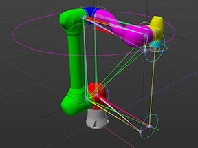
Find the three points/single parallel axis for the main arm and ignore the shapes of the arm. Try to see your previous model in it; perhaps it helps to imagine the green part mirrored as well to the right side.
These three points do not end in the head of the Lilac part. Use the horizontal axis of the red base part, then the one of the small blue part, and the goal is the "end" of the blue part. Anything else will distort the rotation.
I can't see an IK setup that goes from the base to the last part of the "tool" head.
This is all I can say based on images. Please note that I prefer always to get a project file*; images tell me only a little bit.
*If the C4D file is above 1MB and can't be uploaded here as is, please use only DropBox, Google, WeTransfer, Adobe, or Apple Cloud services. Please upload the file as is, no rar or zip. Paste the URL as is (no tiny url or HTML wrapper). Sorry for the long instruction, but safety first. Yes, I will not touch anything else.
Cheers
-
Thanks for the quick reply, Dr. Sassi! Via work, we use OneDrive for file sharing - is that acceptable?
I would love to share some of my attempts - albeit they are all half-baked/messy and, obviously, not working!
~MV
-
Hi MV,
Here is an upload link. I will leave it here for a short time.
(…)I need only the model. No IK.
Cheers
-
Perfect - I just uploaded a file containing the original geometry (I did the color-coding, and attempt at organizing the joints/pivot points), as well as two of my half-baked attempts.
Thanks so much for taking the time to look at it!
~MV
-
Hi MV,
Thanks for the file, I love having something to work with!
Here is the simplest way to animate this arm, as far as I can think about it. Anything simpler would be just a User Data mixer that controls the 6 axes, while the objects would be set up in a Hierarchy.
I hope this tiny IK setup drives most of the motion.
I have placed behind the "Circles" the Rotation parameter name (e.g., R.H) so you don't have to memorize it.
Additionally, when you set up Circles as a Group Parent, consider having the axis Z point in the arms' direction; it makes life easier. Joints are not mandatory in the Z direction, as most tools in Cinema, 4D, work with the assumption that Z is used.
I have animated the rig, but I also used the default position's Freeze option to quickly reset everything.
It is my firm belief that a proper arm aligns as much as possible on each axis, so when one arm higher in the hierarchy has to rotate to avoid perhaps an Euler problem, the Tool on the tip doesn't move in circles. I hope I found the sweet spot in this model as well.
Here is the file back.
https://projectfiles.maxon.net/Cineversity_Forum_Support/2025_PROJECTS_DRS/20250609_CV4_2025_drs_25_CAsd_03.c4d.zipAll the best
Dr. Sassi Sassmannshausen Ph.D.
Cinema 4D mentor since 2004
Member of VES, DCS. -
Hi @Dr-Sassi - thanks for taking the time to look at the file!
I hope I am not missing something key in the rig you sent - from what I am seeing, it doesn't look like an approach like this (which I have indeed tried!) will quite get me to where I need to be in terms of accurate IK control of the entire robot arm.
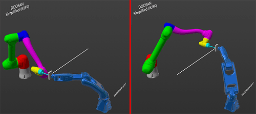
My end goal is to only have to animate the position of the mounting surface of the EOAT (end-of-arm-tool), such that I could draw a straight line without having to animate all the intermediate joints - this is the behavior for actually programming the robot, and I have seen this correctly/accurately "simulated" by a 3rd party robotic simulation software [Visual Components - https://academy.visualcomponents.com/lessons/doosan-robot-connectivity-plugin/ ]
Because all the joints have to coordinate in a non-linear fashion in order to drive the EOAT along a straight line (at any given angle within the working envelope), you'll never really be able to achieve that accurately by manually rotating the joints - even if you save some work by having J1/J2/J3 driven by IK.
If you look at/click on the image below, hopefully it shows up big enough to illustrate what I am describing: the J4 (lavender) / J5 (yellow) / J6 (cyan) all have to coordinate their rotation if the EOAT is to maintain a locked orientation along a straight line. Even if I could get the positions dead on at either end of the move, the interpolated move in-between will not be along the straight line since a default spline within C4D is not the motion profile necessary on those joints to complete a linear move with the EOAT.
It seems to me that there is some kind of IK feedback loop which I am unable to replicate, because the IK-solution for J1/J2/J3 depends on the location of J4/J5/J6, but their orientation depends on the orientation of J1/J2/J3 ... so I have been chasing my tail! Part of my trouble is that I cannot seem to "push" anything with IK ... it is always a "follow-along" setup.
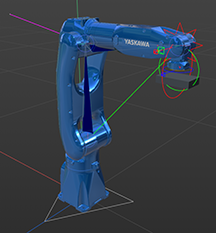
The blue robot is the YASKAWA GP7 I referenced earlier, which I did successfully rig up do this - I simply animated the position / rotation of the EOAT, and the intermediate 6-axes followed along beautifully based on IK and up constraints - but the catch is that here all the joints are in the same plane; the DOOSAN joints are all in slightly offset planes such that my method for the GP7 hasn't been working this time.
I hope that all makes sense! Again, thank you for taking the time to look at it. I can upload the file which is in the screenshot above, if that would be helpful - just send send me another Dropbox link.
Thanks!
~MV -
Thank you, MV, for the reply.
From experience, I know that will not fly. But as usual, I checked if some of the newer features support overcoming those limitations.
There is no 3D setup with many joints (2+) that allows for single or double-axis freedom only (meaning all other axes are locked).
The only example that I could suggest to come close (NOT MATCHING!) to the target is to split the IK and have either a shared Goal or Base.
Example.
CV4_2025_drs_25_CAra_01.c4d
I have no idea, nor have I seen, that this is possible with the IK Tag when a Robot arm precision is required.Sorry
All the best
-
Blast! I was really hoping there was a silver bullet I was missing.
What you described (in terms of splitting the IK with a shared goal/base) is where my last attempts were left in a hot mess. I've gotten close ... but never quite right.
I wish I better understood how C4D differs from something like SolidWorks in this capacity, since I have successfully "mated" up the same robot in SolidWorks such that all the joints know how to orient themselves based on the position/orientation of the EOAT.
But I have not, for the life of me, been able to recreate that behavior within C4D ...
Thanks again for taking time to look at it!
~MV -
Hi MV,
Yes, it would be great to set the object axis, define their freedom, and anything else is handled, with no upper limit of complexity.
Please allow me for anyone reading along to put the idea of comparing these apps in perspective. (Yes, I'm naturally biased here, no argument)
To compare Solid Works with Cinema 4D might have some problems. Given that it has no 6 axis IK toolset to begin with, going by search results, at least nothing that would allow for the required precision.
From my search, not all versions can handle 4 or 5 axes, and depending on the version you use, it costs 3 to 4 times more as a subscription per year. Whereas the Standard version can't provide that amount of axis. So, that brings the price point to four times. Sure, it is a completely different app. Hence, I presume they work great as a pipeline for these workflows.
Typically any number give, so far my search and understanding, is not a 6 single with each used on a different element. Higher learning and massive computing is currently explored to solve more, but there is no sign so far that it can be solved with over the counter computers. Hence it needs some tricks, typically done with a major movement of one and a connected smaller IK.
The IK system in Cinema 4D is developed for character animation, and the few times that was not enough, going by the questions I have gotten over the past two decades, is slim.
If you need something like this and others request the same, perhaps at one point, something complex like 6+ axis IK and 3D support will show up.
Please Share Your Idea here:
https://www.maxon.net/en/support-centerI had to test the rig of course, with an endless Loop
")
https://projectfiles.maxon.net/Cineversity_Forum_Support/2025_PROJECTS_DRS/20250610_CV4_2025_drs_25_CAsd_11.c4d.zipEdit: I add this file to showcase how a 3D IK with Limits would react. While it is not even complete.
CV4_2025_drs_25_CAsd_31.c4dAll the best
Dr. Sassi Sassmannshausen Ph.D.
Cinema 4D mentor since 2004
Member of VES, DCS. -
That's great! Ironically, I work in the secondary packaging industry, so endless loops is pretty much all I ever deal with

I have been told C4D is a "surface" modeler, while SolidWorks (as a CAD package) is a parametric "solids" modeler - near as I can tell, it seems to be the 3D equivalent to raster (C4D) vs vector (SW). I use Okino NuGraf to convert the .SLDASM files into .C4D files, but there is no going the other way.
So there is something about the pure mathematical/formulaic representation of the 3D object (without tessellation), which, in my uneducated opinion, is likely at the heart of how/why C4D constraints don't behave as precise/consistent as corresponding mates in SolidWorks.
I did try a quick test using the hinge object (since each joint only operates in one plane), and aside from some funny jittery behavior, it behaves well in terms of the joints respecting each other (of course, all it can do right now is just fall down and swing uselessly like a limp arm). I am just not sure how I can use the simulation engine to constrain the beginning of that "hinge chain" to a given point/orientation. Not sure if that is even possible, but that would be mimicking the CAD world of SolidWorks.
I hadn't looked into limits on the joints - I will need to try those as well!
Thanks again,
~MV -
Hi MV,
You're absolutely on the right track—your analogy between raster and vector graphics is a helpful comparison. Many CAD modelers are built on mathematical definitions for shapes, allowing for anything from rough approximations to extremely high precision. Engines like ACIS (developed by Spatial Technologies in the 1980s) exemplify how far this can go: they define geometry at a near-perfect level and are widely used in various industries.
The translation of those mathematically precise models into polygons is a critical step. It's where one must balance smoothness, performance, and data size. What works brilliantly in machine tooling, for example, can become impractical in character animation—context always matters.
Your mention of IK (and FK) brings this point home again. Here, FK is often underrated, and when people lean too heavily on automation, it's sometimes a sign they haven't fully mastered the manual approach. I speak from experience—while I have a full motion capture setup, for smaller tasks like animating just a finger, I always go manual. Starting the whole setup while knowing that cleaning up work is needed makes that an easy decision. It's quicker, more direct, and often gives me the control I need without the overhead.The same principle applies to Dynamics and Simulation. I used the first Maxon Dynamics Module released around 2002, and while it opened new possibilities, it also changed the nature of the questions I received. Many artists hoped dynamics would replace the need to learn animation fundamentals. But dynamics has no understanding of artistic intent—it's physics, not storytelling. This became even clearer when the Bullet system replaced the earlier module. The ability to throw something into a simulation was seductive, but the results often needed art direction—and that's where limitations surfaced.
Cinema 4D is not a game engine in my book; it's built for artists. So, over the years, we developed tricks and workarounds to regain expression control over simulation results. Ironically, bending dynamics to follow an artistic vision can take longer than simply animating things manually. That trade-off between control and automation is always present.
So, thank you for bringing up the raster–vector analogy. Once precision is translated into polygons (with inherently straight edges), we rely on smoothing methods to hide the loss. But the process is rarely reversible—you can't easily turn polygons back into their original mathematical perfection that the formula had.
As for robot arms and advanced rigs, I've tested many versions over the years, including complex constraint-based systems. Our team even ran internal challenges to find the best approaches, and problems, some of which led to improvements in the software. Here's one example from that period:
https://www.youtube.com/watch?v=5dNmL-NpU_wBut challenges remain. For example, dynamic or simulation systems have no built-in understanding of problems like gimbal lock or Euler angle issues (see: https://en.wikipedia.org/wiki/Euler_angles). Connectors and joints work well to a point, but there are limitations.
That said, I won't discourage you. Quite the opposite—I'm glad you're exploring this. If anyone finds a novel solution, it might just be someone like you who's willing to dive deep into a problem others have walked past. Just keep asking: what's the actual goal? Is it a render, an animation system, or something else?
You might find useful insights in academic research—there are papers exploring joint systems with up to 20 degrees of freedom, sometimes even with shared code examples. For those cases, I'd recommend visiting the Developer Café, as our current forum doesn't support code sharing due to security policies.
Whatever direction you choose, I wish you the best. Choose your goals with care, and go deep. That's where the breakthroughs happen.
My best wishes
P.S.: CV4_2025_drs_25_CAsd_41.c4d
___ .CV4_2025_drs_25_CAsd_51.c4dDr. Sassi Sassmannshausen Ph.D.
Cinema 4D mentor since 2004
Member of VES, DCS. -
@Dr-Sassi - thank you! I am still tinkering in between projects as I am able. I will see if I can implement one of your dynamic "control" methods here, and see what happens!
Thanks again,
~MV -
Hi MV,
Thanks for the reply. You're very welcome.
The Dynamic examples were more to show their limitations, as you mentioned those that you like to explore dynamics. I will not hold anyone back, as I always live under the impression that there must be a way when I get questions.
If I have any limitations (even with six degrees – three of them are engineering degrees from German Universities, not meant as bragging, just to put some light on my background), I do not want to share any limitations as a stop. I would be happy to see that solved. However, I also want to point out where the limitations are, or at least where I see them.
In one file (above), I placed little squares to showcase that it gets quickly unstable. Of course, the iterations could be set much higher, but I do not have the computing power here to experience that rewarding experience.
Since the head alone needs all axes of freedom to be positioned in any way (P.X, P.Y, P.Z, R.H., R.B, R.P), it creates a lot of stress on the "locked" axis down to the base of solved with dynamics. Which is similar to the problem with IK. I stick for now with my recommendation to invest the time in a good rig that allows for an easy adjustment with sliders or other HUD elements, meaning manual animation. The example I have shown with IK gets you there to a certain degree even.
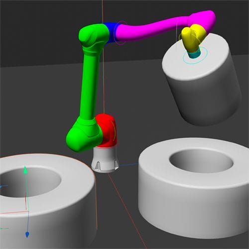
My current idea is to reduce the complexity first, thinking of two spheres. One is centered around the base, and its radius is based on the second one. The second one gets its primary position from the first one while having the position freedom of the radius (the main IK arms of the robot)
Its orientation is based on a target that can be placed where the "head" needs to be. Similar to BB-8, but with a diameter-changing body.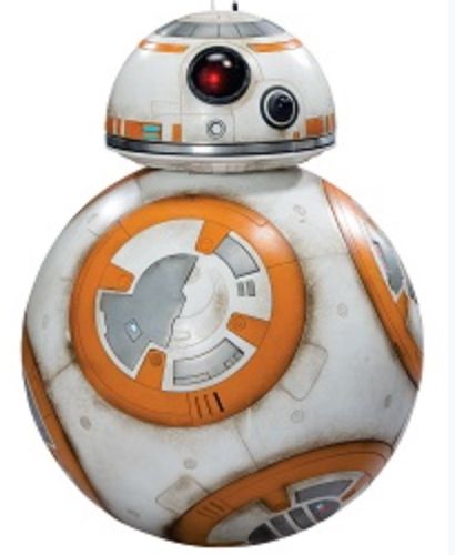
All the best
-
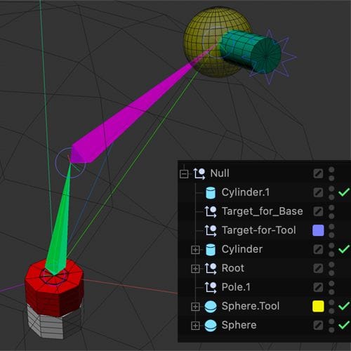
P.S. Here is the BB-8 translation of the setup, as a source/collection of ideas.
The Yellow sphere, can be positioned, while the Target_for_Tool defines the direction of the tool. Both have Layer colors applied to spot them quickly.
File …_61 is static, with the two animated parts having a Position Freeze, so they can be reset with the PSR-Reset.
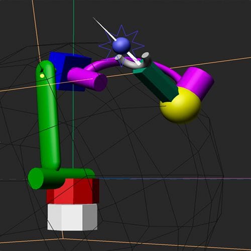
CV4_2025_drs_25_CAsd_61.c4dFile …_63 is filled with shapes, and yes, there is one short cut in it. Priorities are updated
CV4_2025_drs_25_CAsd_63.c4dFile …_64, just for fun, 240 frames and a longer animation
CV4_2025_drs_25_CAsd_64.c4dPreview:
https://projectfiles.maxon.net/Cineversity_Forum_Support/2025_CLIPS_DRS/20250621_CV4_2025_drs_25_CAsd_63.mp4
As loop and longer
https://projectfiles.maxon.net/Cineversity_Forum_Support/2025_CLIPS_DRS/20250621_CV4_2025_drs_25_CAsd_64.mp4
The tool head will show an Euler angle problem if placed exactly vertically to the target.
Here, the idea was to define a target and then just position the Yellow sphere (Keyframes only for Position).
This allows for a tool axis movement, as seen between frames 100-120 in file 62.
I found that here is the best compromise between IK and manual setup.
You talked about that axis are not all on one plane. I would check with the Company of the arm if that is the target and why this was done.
Colors are as much as possible used from your example image
My best wishes
Dr. Sassi Sassmannshausen Ph.D.
Cinema 4D mentor since 2004
Member of VES, DCS. -
@Dr-Sassi - thank so much for this, as I wasn't following the BB-8 description exactly when you first mentioned it (and again, I am jumping in on this between projects, so I apologize for my sporadic responses).
The latest, "63" file looks to be the most promising for what I am after. Not the end of the world, but I am getting a bit of a priority lag with the pole null, and was curious about eliminating that ... not sure if it is possible with this exact setup given the order/combo of constraints/xpresso/matrix?
I haven't gotten to dig into it just yet in order to fully digest it, but am anxious to try it out with my DOOSAN geometry. Regarding the DOOSAN design, I am not entirely sure what the rationale was behind their offset design - it is a "collaborative" robot, so there may be something in relation to the types of servos they have to use in order to achieve sufficient "sensing" during low speed operation? Not likely, but the only thing I can think of off the top of my head.
Edit: I didn't see the file 64 - I'm going to take that one as my starting point! Still looks like there is a slight priority lag about which I am curious.
Thanks again!
~MV -
Hi MV,
Yes, you got that right; the 63 had some unsorted priorities. I left them in as I moved on with 64 to fix those. Sorry if there was any confusion based on my doing.
I'm glad you brought that theme up, as I know the (mostly) where the limits are, but there is, more often than not, a way to make a workaround of some kind that might come close.
The head or the "tool" needs the freedom of 6 axes alone, which is not doable with normal input devices directly and, in that way, hard to direct since I do not have a "Space-Mouse". So the Target-Tag use (as your headline suggested) is a good help.
My best wishes for all the projects you manage at the moment.
-
Hello Dr. S,
Sorry this has been a fair bit, and I have not been able to dig into this deeply enough to quite get this approach functioning (still having some issues with immediate flipping of some of the joints using the up/aim constraint since there are two mathematical solutions for a given segment of the IK created with the constraint tag). So still working on that front, chipping away at experimenting here and there!
I just recently came across the Interaction Tag, and was curious if you had a knee-jerk reaction to using that in conjunction with IK ... wondering if there is any potential of semi-recreating a more SolidWorks-like behavior by defining the joint rotations via pose morph ... but I have no knowledge of the fully capability/limitations of the pose morph/interaction tag combo.
Thanks so much,
MV -
Hi MV,
Sorry, that you can't get it in the way you want it.
I can't see any option to overcome the widely discussed problems via the Interactive Tag.
Yes, there are formulas, as mentioned above, but there is no option to use them, except perhaps via coding. Since code is not allowed in this forum, based on security, that would be a case for the Developer Forum. But the Developer forum is not a "request-code-delivery-forum", AFAIK.
What you try to do will not work in the way you want it, from my point of view.
At this point, please contact tech support to get a second opinion.
https://www.maxon.net/en/support-centerAll the best