Modelling opera tent
-
Hello
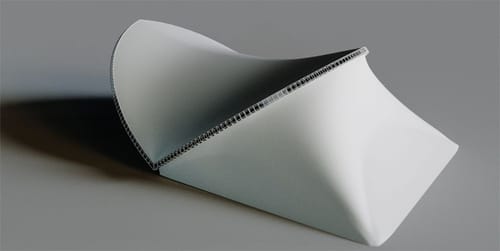
I'm trying to model this opera tent for a project, but I'm getting stuck because it feels like the dimensions are not equal across the curves.
I'm trying to use arcs to generate the two facing truss structure that are composing the main "shell" (I don't need to create the covering, just the structure).
Is there a way to extrapolate the actual curve from these measurements?Here is the project I started
https://www.dropbox.com/scl/fi/wl78tb0g3szrab8h4q887/OperaTent.c4d?rlkey=ksa9tyl7llnll089bd6km8ln0&dl=0And here is my document with measurements and drawings.
https://www.dropbox.com/scl/fi/prrueqrb3lo3u5ogps7h9/1_ZSB_Opera-Tent_18X21-Single_Grundma-e.pdf?rlkey=xv341fquqdmcsutqmjp22teqg&dl=0Thanks for any advice!
-
Hi AlexC,
The "blueprint" contains all the data needed to create this. Which can be easily integrated into Cinema 4D; I left it all in the c4d file.
https://projectfiles.maxon.net/Cineversity_Forum_Support/2025_PROJECTS_DRS/20250617_CV4_2025_drs_25_MOot_01.zip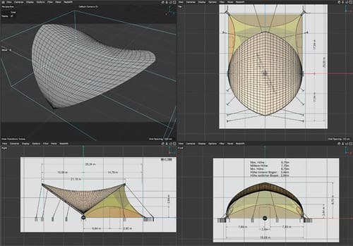
If the curve fits all three orthogonal views (Multi-Views, or since the Drawing was in German, Dreitafelprojection), the resulting Spline should be OK. Why shouldn't it be? Because the plan and my exploration are not in agreement either with the measurements or the drawings. Minor differences, but noticeable enough for me to mention.
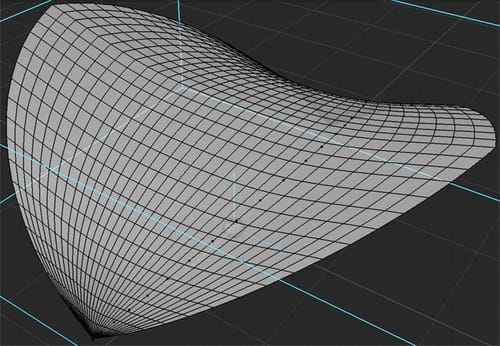
I have modeled the main Tent's surface; I hope that helps. Let me know if you need more support on this.
The sphere in the scene is more to orient myself, it can be deleted.
All the best
-
P.S.: Since I love modeling, here is the complete shape.
Perhaps place it in the folder that I shared earlier so the blueprint is connected.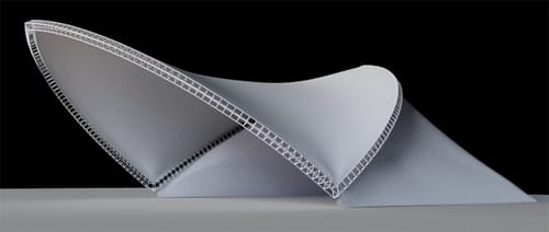
(The main frame can have diagonals if needed)
Enjoy
-
Thank you Sassi, this is incredible. And extremely useful! May I ask how you managed to get the exact shape of the truss curves? This is what I was getting stuck on...did you use the blueprint as a background to extrapolate from?
Again, thank you so much
-
Thank you very much, AlexC.
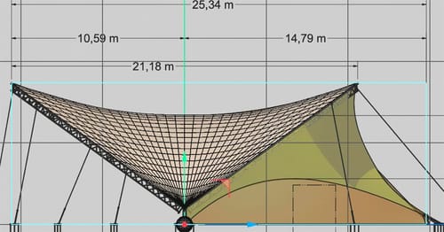
The first step is to use one matching drawing of the blueprint for each of the three orthogonal views. This can be done by simply taking a screenshot of that area and using the image or by creating those "crops" in Photoshop.
They have measurements in them, which I placed into the cube. From there, each view can be scaled, offsetted, and rotated if needed. While you click on the top bar of each view to have them active, use "Shift + v" to get into the dialog (Attributes)
The second step is to start with a simple Bezier curve (two points only and "drag" the mouse for each point to get longer handles.
Start in one view to define a quarter of the "bow", then go to the next, and then to the third. Typically, you have to go through that routine at least twice.
If that spline matches a quarter of the construction, You can use the Symmetry Object to get two and another to get all four.
The current State of the Object for each Symmetry will result in four Splines that cover the four. I connected two each time and copied it vertically in the middle while scaling it down.
I noticed that three do not define the shape well, so I created two more copies and rotated those (Spline 1 2 and Spline 1 4). Rotation is performed by selecting all points of a single Spline, then using the Rotate tool and adjusting the Axis in Attributes in X, Y, and/or Z to achieve the desired rotation point.I hope the first file I shared helps to support seeing those steps.
All the best
-
Hey Sassi, thank you! I missed this. Super clear explanation. I was thinking I could find the curve via the arc settings, but obviously it is not a perfect curve and your method makes perfect sense.
Thank you again!
-
You're very welcome, AlexC.
Before I studied architecture, I had three years of training to become a Technical Drawer; to create or read those "blueprints" is second nature to me. Which makes me confident to have shared the fastest way. Thanks for checking this out.
Your intuition about the Arc was not off.
It can be done with an Arc, four of them, but the problem here is that the center point of each Arc is not in the center of the tent. This causes a lot of trial and error, especially since the "blueprint" has no orthogonal view to this quarter arc, like when it lies on the ground to be assembled. The radius of an Arc here is 12.80m-13,50m (+/-) based on taking it from the "blueprint". Using the three orthogonal view (Multi View) re-engineering method is faster and has no guess-part in it. Anyway, your intuition was good.Enjoy your project