Modelling with Camera Projection
-
Hello
I'm working on a fairly simple (?) concept, to take a picture of a room, projection in on some simple geometry using camera calibation, and then adding some surfaces that are just supposed to act as "mirrors".
What I'm trying to do here it to try to make all the windows into reflective surfaces.
However I'm not sure if something has changed since Redshift integration, but I'm finding it pretty hard to navigate and place surfaces. In the attached file, you can see I started with the left windows, but they are completely off, and I'm not sure how to find the right position for them in space.
What are some tricks for navigating this projected space?
https://www.dropbox.com/scl/fo/y2z7pdh9d433fskovfovb/ANuUKuBdXLRWJOI2b2DnKaU?rlkey=3tu2kwi8u5co3l8oj95wg3jlq&dl=0Thanks!
-
Hi AlexC.,
Thanks for the files, always the best way to work.
Private note:
Camera Projection, my all time favorite.")
First reading a long it felt like the stpmj "barn.
https://www.archdaily.com/770303/invisible-barn-stpmj
/private note end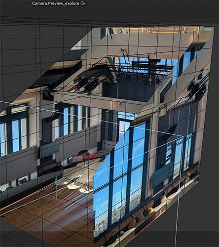
Since I write in a forum, I have some general notes in the text, for anyone reading along.
When the lines are straight on the side, then that is a good sign.Missing lens-distortion, or any information what happens to this image before (never accept png or jpg for pro work, ask for the raw file, then you know it is not cropped or even worse "un-distorted in post).
I use typically the Standard render settings for this. I get a lens of 21.5mm roughly. Your camera indicated a tilt shift lens. I can't find any evidence for that. But again, any alteration of the image between shooting and distribution poses a significant risk for professional-level work. Sorry to stress this here, but I write in a forum.
To get the geometry aligned I enjoy having the Geometry Axis (Asset Browser). Set to a known "corner" of the object, allows then to use the size parameter to adjust accordingly.
I had no measurements of the set, so I had to make some guesses. I did it anyway, but I want to point out that this isn't based on real size.
The windows need to align to the "cube, then placed into one corner, and adjusted in size to cover the window area.
The material for Reflection is Redshift, and the Render settings are now set to RS.
Please the file into your project folder so the texture will reconnect.
CV4_2025_drs_25_CPpt_01.c4dEnjoy your project and your weekend.
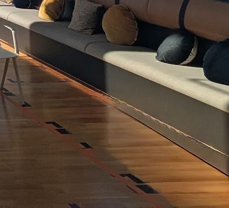
P.S.: In the right lower area, floor to bench, there is an part that makes no sense, it feels like the floor is tilting.
-
Hello Sassi
Wow, this is perfect! I need to do this for some other photos and so I wanted to double check on your process
1/You worked in standard renderer, is this the better way to approach than working in RS with interactive render mode in the viewport?
2/I created the camera using the camera calibration tag. Is that a good approach?
3/The cube that was in my scene was at the right dimension for the room, based on my plans of the space, but. I can see that yours is very close.
4/I noticed your window polygons are all using the Geometry Axis of the room cube. Is that the way to place things accurately in space?
Thanks for any insight on the process! And thank you for the scene file! -
Hi AlexC.,
Thank you for your reply.
1
The camera Calibrator works with both rendering settings, ST and RS. Sorry for the confusion.
2
With images, that is my preferred way, whereby it requires perspective lines (like a shot in the forest would have none of those typically)
3
I had no idea that your cube was set along a set survey measurement. Yes, I guessed it.
4
This is an older technique, from Tim Dobbert's book (Matchmoving). With the Geometry axis, you can set the Object axis to one corner of the object. Then align the edge with the vertical line. Then rotate the object until the other edge that is 90º to the vertical matches. Now the dimension parameters need to be adjusted. That's it.
5
If you have more of those, and as I mentioned, the original image is often key, since I know you work on a top level with your projects, here is a tip: If you have a hi res image, you could take that image into photoshop, add an layer and paint the windows white on that layer. Next, set a black layer below and merge the two. Now you have a reflectance layer. This can be used if the camera projection is set up correctly and the geometry matches the window position. This allows you to exclude fine details from the window, similar to a plant in front of it.My best wishes
-
Fantastic, thanks Sassi, I will try this approach with another shot!
-
You're very welcome, AlexC.,
Always a pleasure.
Enjoy
-
Thanks Sassi
Out of curiosity, when you first opened the project I sent, what seemed to be wrong? Was the overall camera projection and position correct?thanks!
-
Hi Alex,
When I look at the camera, it tells me ~85mm focal length. My value is ~21mm.
The lens was set to a shift lens with a maximum of 320%. My Canon TS-24mm (kind of a standard) allows for a shift of less than 100%, going by usable results. Hence my suspicion about the validity of the Offset/Shift.The cube that describes the simplified cube of the space seems 90º based, so the cube is plausible. With this, and the cube considered correct, the windows need to sit on the Cube "Planes". They don't.
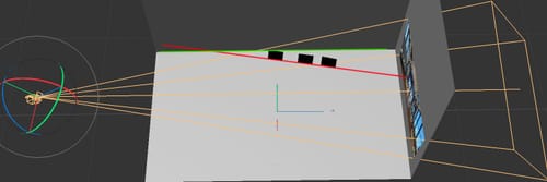
To "draw" or align from the camera perspective, with no cube alignment (in this case) provides no guidance where these windows might sit. It can even have different orientation, as the points of the four corners sit on a ray from the camera aligned with the window corner, while not providing any distance to the camera. Hence, the result can have infinite variations.
The image shows the mismatch between the image and the cube; compare the image above.
The complete image is projected to the opposite "Wall" including the content for the side walls.
The windows are aligned based on that on the red line that I included, and the green line should be the one used.
Is that helping?
Cheers
-
New topic moved
https://cineversity.forums.maxon.net/topic/2030/camera-from-scan
Please one theme per topic. -
Referenced by
 AlexC
AlexC