Fracture object texturing both sides
-
I've tried posting on Reddit but so far haven't had any replies so trying here too.
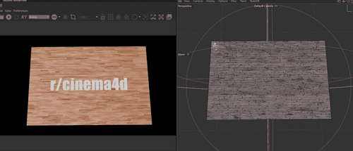
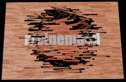
I'm using the partition wooden floor generator from "mxn_drop_2024-03-01" in the asset browser with a slight few adjustments. I've added caps to the extrude as I want a different texture on the bottom faces that will be revealed by a plain effector and a growing spherical field.
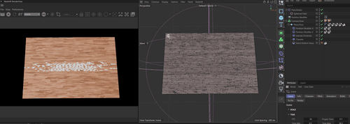
The problem is that applying the 2nd texture in the same manner as the 1st (UVW projection, no tiling, fit to object) doesn't display the new text correctly. I've tried applying the textures on the original plane directly whilst creating a polygon selection for the bottom caps but no luck there. The second pic should read "please help".
In my mind I think it could be a UV issue? The bottom faces aren't aligned the same way so way so the rotation of each plank breaks the texture. Do I need to find a way to break up the texture before applying it so that when it rotates it looks correct? I've been trying to find a way to stick the texture in the ideal orientation at the end state on the back faces.
Is there a way of recreating the setup but with a cloner instead? (Would that even be useful?)
Any help would be much appreciated, I feel like I could be missing something obvious but I don't often use fracture objects so I'm a little lost!
-
Hi millsy05,
I'm not clear about your set up, any changes? As the original file as no bottom polygon, hence I can't answer the second image question completely, if at all. If you like to rotate the planks and have after a 180º a logo, that might not work with this set up.
Please have a look here
CV4_2025_drs_25_TXpf_11.c4dThe key is to enable Create Caps in the Extrude Capsule. So you get a full body, not just an open box.
I have introduced a selection tag for the main material, which should sit on the right of the Object Manager.
This Selection Tag has a Formula Field, including all but the segment/polygon zero.
I have reduced the scene dimension to get a clear view.Fingers crossed that this will work for you.
If not, I need a file, to see if you made changes
If an example is below 1MB, it can be attached here as a c4d file (never use zip, rar, or anything here in the forum.
Given that the file is larger, I will touch only DropBox, Wetransfer, Google, Adobe, or Apple services for security reasons. Please, no tiny Uad, no zip or rar, e.g., for the upload. The URL is just pasted here, not HTML -hidden Hyperlink. Sorry for the long text, it is all about security.Enjoy your weekend
-
Hi milsy05,
The simples workflow might be this two step process.
Here is the simplest way to work with textures and two sides while the clones are individually rotated 180º, presenting the "backside" readable.
File 01 is the image production
Preparation, switch off Chamfer, Extrude. Rotate the clones 180º individually so the wrong image is rendered. (the "180º" Plain effector does this)
This image should be supplied as an Emission with a weight of 1.0 and all other channels set to zero.
The Partition Modifier has a gap size of zero for this rendering.
A camera with a focal length of 36 mm centered over the image at the same distance as the width.
The render size equals the ratio of the rectangle up for rendering.
Global illumination is off; it would only take more time.
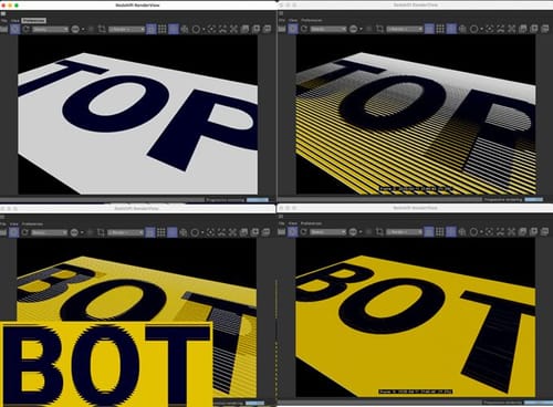
The wrong image is rendered and swapped out with the correct one.
The Formula in the Polygon Selection is ID>0, allowing it to cover all but the bottom sides.
Leave all the settings safe and use them for additional image productions.
Save now incrementally to get file 02As file 02 shows, the Extrude and Chamfer are back on, and the Extrude has Create Caps enabled.
The Top and Bot(-tom) files are separate Materials, and one has the Selection Tag with the Formula Filed set to ID>0. This selection Tag is in the Selection field of the Top Material that sits on the right in the Object Manager.For all minor details, here is the set up of file 01 and 02
https://projectfiles.maxon.net/Cineversity_Forum_Support/2025_PROJECTS_DRS/20250411_CV4_2025_drs_25_TXmg_01.zip
Enjoy
-
Hi @Dr-Sassi and a huge thank you for getting in touch, sorry for not replying sooner, it's been a busy couple of weeks!
I can't see an attachment in your second post, do you still have the files to share again? If not, here's a project file that hopefully illustrates my issue better.
https://we.tl/t-ashwOPnvXL
Thanks once again.
-
Hi millsy05,
Thanks for the file. The rotation matters; in the example above (file is added), the rotation was vertical.
Your example is horizontal. (as Photoshop would describe the rotation)
https://projectfiles.maxon.net/Cineversity_Forum_Support/2025_PROJECTS_DRS/20250422_CV4_2025_drs_25_RSrt_11.zip
In each case, the wrong view of the Material must be rendered and then applied instead of the original. then it works.
The Bottom Selection is unnecessary; make sure to the Bevel off when rendered. It is the Camera with the Frame_90 in the name, and it is the same for the render settings.In the file, I have only a small texture; just render and replace the small one with a larger one, e.g., 4800x3200 pixels.
No single texture or approach would work in both rotation directions.
All the best
-
Hi Dr. Sassi, this is great, thank you so much.
(I actually had initially attempted to break up the texture but I couldn't work out how to do it correctly. Glad I had the right idea though!)
-
Hi millsy05,
The first step is to communicate the problem and then find an idea.
Feeling that there is a way to make space for the idea to grow into is important.
Great that you have that! Keep going.Thanks for your reply.
Cheers