How to Clone Cables Along a Scaled Rounded Rectangle with Alternating Materials Without Sweep Distortion?
-
Hi everyone,
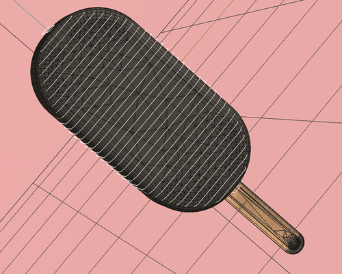
I'm trying to create a setup in Cinema 4D where cables are cloned along a rounded "not-even" Cube. See Screenshot
What I would like to have:
Cables (with Sweep objects) cloned evenly along this shape.
Each cable should have alternating materials (e.g., one black, one red, one black, etc.).
The Sweep objects should maintain consistent thickness (no distortion due to scaling).
What I’ve tried:
Cloning Sweep objects using a Cloner → but the Sweep objects get unevenly distorted because of the varying scale of the rectangle path.
Cloning just the path splines, then using a Connect Object to feed into a single Sweep → but then I can’t assign alternating materials anymore because everything is treated as one spline.I’m looking for a clean way to clone cables along a scaled path that:
Avoids Sweep distortion.
Allows alternating materials per cable.
Is still parametric if possible.
Has anyone tackled a similar setup? Would love to hear if there’s a good workflow for this!Thanks in advance!
-
Hi Simonsays,
Sorry for the delay, but we had a Global Summit. Thank you very much for the file.
Is this close to where you like to go?
CV4_2025_drs_25_MGac_01.c4d
Please let me know if there is any question that the file doesn't answer, or if you need something differently.
All the best -
Hi Dr. Sassi
Thank you very much, that's exactly what I need.
Could you kindly explain to me what exactly you did?
What does ‘RSMGID’ stand for in the User Data Node?
I understand what the FX Mod Node does, but I don't understand why and how I could use it otherwise.
If you have a little time to explain these things to me, I would really appreciate it.
Best regards
Simon -
Hi Simon,
Of course, I will explain that.
The FX ModNode is the Modulo function. It divides the input by the number provided (Divisor) in the node and outputs the remainder only. In case above the Fraction object is set to "Explode and Connect" which provides each "ring" as an object with its own ID number..
This number is then provided in the User Data Node. When you click on the User Data node, there is a Preset with some standards Redshift RS MoGraph MG User ID (RSMGID). This could also be USER Data on an Object; then, you must type its name there.
So, the User Data provides an ID, typically starting with zero and then counting up: 0, 1, 2, 3, 4, 5, etc.
To switch two colors, we need to run the Color Switch using 0, 1, 0, 1, 0, 1, etc.
Let's take ID 3 and use the entry (Divider) 2, which means 3 divided by 2 = 1.5. For our needs, it can be divided one time and have a remainder of 1. If we do the same for ID 4, then we divide 4 by 2 = 2. It divides two times and has no remainder, meaning the result is zero.
Here is another source
https://youtu.be/Lf7JaGaeDP4?feature=shared&t=780The Module node is often used to turn progressively counting sequences of numbers into smaller loops. It takes only color 0 and color 1.
If the divider were three, then you would get three colors, as the remainder would be 0, 1, 2.
Why does the ID number start with zero? In the past, computing was expensive, and every part of each binary needed to be used; hence, everything typically starts with a zero.
Please let me know if that was clear and if you have changed the number to something else and got different results, hence why the file has all ten fields set with color; typically, they are all white, but I hope it invites you to explore.
Please always ask; I'm happy to dive into it.
All the best