Camera from Scan
-
Admin: This thread was split, as a different theme was started. Ownership transferred to AlexC.
Part 1
https://cineversity.forums.maxon.net/topic/2023/modelling-with-camera-projection -
Hello Sassi
Yes, that helps a lot. One thing I noticed is that if I start the camera calibration using Redshift, I get a really strange texturing effect, whereas if I am in standard renderer I can see the camera projection much more clearly.Now I have a bit of a challenge. I had to get images not from a camera, but from a Matterport 3d scan. Meaning that the images don't really have any lens information, they are screenshots from a 3d camera...I still seem to be able to get decent results, at least for quick and dirty placement of objects, but the lens is so wide that any cube I put in the scene looks like a rectangle, even though the objects in the Matterport view seem "ok".
Do you have any recommendations on working with that type of image?Here is a scene I am working on now
https://www.dropbox.com/scl/fo/umvcogd3048r13hfuk74h/APGoIeCJ-6HgDhwJhosScIg?rlkey=rvpwwv1qlbltfm0cb92a66wpz&dl=0And one important comment...The images are also manipulated in Photoshop to remove the furniture, as I have to place LED screens and projection screens etc..in the space, so that is why in the first project file you saw that strange "dipping" in the floor, it comes from the Generative Fill tool in PSD. Here I included both the "raw" screenshot (in the tex folder) and the modified version, but I don't know if it makes any difference in this case.
Thank you!
-
Referenced by
 Dr. Sassi
-
Hi AlexC.,
Thanks for the files and for using drop box.
If you like to work with a 360ºx180º scan, ask for the full Equirectangular.
Here, the lens height would be the most crucial part, while set surveys (wall distance to the camera 90º) and some larger objects, like a doorframe, in measurement help. A little note, if the room is based on 90º wall corners or different, it will help)With the equirectagula and the height of the lens, while assumed leveled, an equirectangular mesh (A cube and a 360 camera) can be overlaid on the image to see if it is "OK". If so, the image can be mapped on a sphere, not tiling, etc., and with a camera at the absolute exact position of the sphere center, you can take an image, which should work as the best option with this. The camera's data is now very crucial to memorize, to see if the Camera Calibration works as it should.
Please note, as with any transformation of a pixel, other than a move of one pixel (left, right, up, or down), the quality lowers. The scanner stitches the image, first loss, placing it in a viewer (the sphere) and takes an image from it, second loss, using that in a camera projection, third loss. If any other post is done, to change the size of something, the next loss. Sometimes it makes sense to use the original Equirectangular and project it as spherical onto the geometry, if all steps were precise, that helps the final quality.
As in the thread before, I had no lens profile (yes, one could create one for a scanner), I had zero measurements (my impression, it is larger than in my example), and no idea about what field of view was used to create this, or waht ever happens to the image along the way.
So, lots of uncertainties.File:
CV4_2025_drs_25_CPfs_01.c4d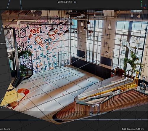
My best wishes for you project
-
Thank you Sassi, as always this is a fantastic way of getting a deeper understanding of how this works.
One thing I'd love to understand better is the starting point. As you said, you didn't have any info on the room size, but somehow you are still able to make an accurate representation, and without distortion!
For this image, I didn't have access to anything other than a website that has a "doll house" of a space created by Matterport, so no real info on anything.
But I did have the room size, which is how I made my cube. However my camera placement was clearly off, and the geometry I was adding was really distorted. How did you get such a clean camera position and no distortion?
In this case, I don't need quality so much, as the work I'm doing is more illustrativeThank you again! I really appreciate looking at these files and seeing your method.
-
Hi AlexC.,
When I think back, two decades ago, you asked for a staircase for a theater set in the same city. With your vast production experience, I know you have all the parts needed to get this done, but to get the best out of the Calibrator, please allow me list it clear some points, just in case.
The Camera calibration tool has an option to set the size. Like take any door, it is rarely below 200cm, or way above 260cm, of course, exceptions for large doors are given. The counter in the last image might be 80-85cm, or a chair around 45cm. Things like that help me.
The Calibrator takes all the data and tries to make sense out of it. Meaning, sloppy placements, or not providing X, Y, or Z, axis (shift click on the Lines until R, G, or B, appears (see world axis of the project), will not lead to good results.
If one axis has a measurement, it works for the whole model. However, placing axes that have little perspective value might change the precision.
Perspective lines that would cross soon and at a large angle, are more precise. If the angle is small, the possible crossing point (in distance) of the two lines will be more more "fuzzy". Exploration: Draw two lines on a piece of paper with 3º and one pair with 90º, define then where their distant crossing point will be, they often do not cross in the image. Is that always simple? It's not.
Another point is that all perspective lines that are horizontal typically indicate eye or lens level (Tilt-Shift lenses might tell you otherwise, or lenses with strong and/or mixed distortion.) But those are a good orientation to check if the established camera is OK.
As mentioned, crops from images, or "lens-un-distorted images, are less useful, or not useful at all, distorted images with a lens profile are useful.
Not knowing the sensor size and focal length leaves one in the dark, except when being able to read what lens was used, even roughly, might be supportive. When you get no set survey either, then the people providing it have no pro-level delivery in mind, sorry to say that, but that is just not really how it works on a certain level.
Always ask yourself: Is it plausible with what the Calibrator came up with? If not, start over, there is often not a quick fix.
In short, when we turn the world (3D) into an image (2D), we lose information and rectangles are no longer drawn as 90º geometries (Exept we look in a perpendicular way to it, and typically when in the center. If we correctly project those trapezoids to a polygon, then the show up as a rectangle again, as we move them from tehir 2D "frozen" state into a 3D again.
In the end, if you do not define a pin, the model is somewhere in space.
All the best
Edited for clarity 07:21 pm Pacific.
-
P.S.: I try to find a way to connect all your knowledge about Camera Projection.
This is a test; I have prepped two Plane Objects, animated, that show two main effects.One that the projection plane is oriented correctly when a rectangular window appears as it should.
The second one aims at a more "abstract" understanding: while oriented correctly, the distance can change without altering the window frame ratio or distorting it, but the position in space, compared to the projection camera, increases wildly.
Just a demo. Please place it in your folder so the texture connects.
Everything is color-coded for a simpler demo.

-
Thank you Sassi, for this file.
I'm a bit confused by what is happening in plane 2, how is it staying so perfectly aligned despite all the motion? -
Hi AlexC.,
You're very welcome.
I'm not clear which one is plane 2. (The spy cameras are un-usual observer)
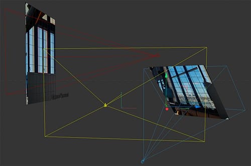
So let me answer both. In the small image on the left is a demo about even it is perfectly aligned still doesn't "know" its position in space, (or more precisely the distance to the camera/projector). The rays from the projector get bigger as they project further away while spreading. Perhaps it becomes clearly when animated and viewed in the top editor view.
I intended to emphasize the importance of the set survey, including details such as camera placement, height, distance from the walls, and other relevant measurements. When this is clear, it becomes clear that all depend on each other.
The one on the right shows that only with a perfect angle to the camera, an undistorted image is re-created. If the plane aligns with the wall (or the windows), then the orientation is correct and the window is presented as it is in reality, a rectangle. (Note we identify a trapezoid shape in a photo as rectangular perhaps, it is typically distorted.)
Both examples, distance and orientation, provide the foundation for effective camera projection.
The windows are all rectangles in the 3D real world. When the image was taken, the "drawing of the windows was no longer rectangular, baked in 2D as a Trapezoid. With camera mapping, we "re-dimensionize" the shape again to a rectangle. If that is clear, the base of the Camera project is well grounded as a mental model in someone. That is what I tried to do here, which helps (hopefully to feel easy with this. In the late '90s, a good friend in Berlin introduced me to Camera mapping. It took me a while to understand what he did. That was pre-YouTube, and Handbooks were shipped across the Atlantic with a 6-week delivery time. Hence, the long time it took me to translate that inside of me.
Nearly three decades later, I hope to retain this memory as vividly as I felt back then, to clear all obstacles for others regarding this powerful technique.
The relevance is not outdated; for instance, if the concept is understood, the idea of LED studios (the next level) is just a step away. I found it quite useful since.
Let me know if that answered your question.
Cheers
-
Hello Sassi, I have been traveling and haven't been able to fully dive into your response, but I am going to study it carefully as soon as I get back. Thank you very much for taking the time to make such a through explanation!
-
Thank you very much, AlexC.,
Enjoy your trip, and please let me know if you have any other questions.
I'm happy to look into it.My best wishes