Can't properly bevel the edge of a boolean
-
Bevel help.c4d
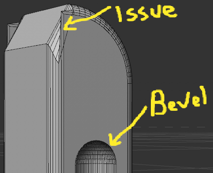
I'm trying to bevel the rim of a boolean that is created with 2 extruded splines. I've tried adjusting the spline's Types and Intermediate Points. I've also tried making the boolean object editable and applying a Bevel to the object, as well as trying to select the edges and trying to bevel.
-
Hi miss-bear,
Thanks for the file, and the clear instructions.
The Boole Tool is limited. For great models, I try to avoid it.
What needs to be done causes more work if you don't want to use the Volume modeling route.
I have modified the Cylinder that creates that half Capsule "cut-out".
It has a band of equal height polygons to allow for Bevel. The current state would not create any usable results. I used to Extrude tool (M~T) on the flat side after made editable.Then I moved it inwards to provide that equal polygon ring to the Boole result. The Boole selected: Object Manager> Object> Current State To Object.
(Bevel was off during that. Two objects, select both Object> Connect Objects and Delete)
The resulting point was all over the place, so I used the Weld Tool to return to the points that the Cylinder had before. (M~Q).After that, I selected the edge (Loop) and used a Mesh> Edge to Spline.
This Spline helped me as a "Field" in the Point Selection Tag (Radius).
This selection allowed me to use the Optimize Tool without harming other parts.Then I scaled the Spline I created before and used it as a Knife (M~K) while pressing the control key with the "mouse" over the Spline and the Object selected, and in Polygon mode.
This allows me to build another ring of Polygons. With the previously created Edge Selection Tag, I limited the Bevel Deformer.
(Not needed, but I couldn't resist the second ring: I used Remove N-Gon.
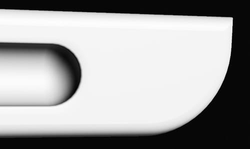
This gave some triangles, so I used the Spin Edge Option (Mesh menu) and the Dissolve for some edges.Please have a look here:
CV4_2023_drs_23_MObv_01.c4dIf I had to do it from scratch, I might have started with the Cylinder and used the Extrude Tool in Edge mode to shape that form from it. That would have avoided the N-Gons from the start.
Cheers
-
Hi Dr. Sassi,
Thank you (as always) for the help! The result you provided me is exactly what I wanted. I'm trying to recreate your results by following your steps and have a couple questions.The Boole selected: Object Manager> Object> Current State To Object.
The resulting point was all over the place, so I used the Weld Tool to return to the points that the Cylinder had before. (M~Q).When I do this, it creates 2 disconnected meshes: the overall shape and then half cylinder shape that is the "negative" space resulting from the boolean. Here are the pieces (I moved the one piece out to better illustrate):
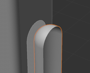
Are you using Connect and Delete Objects to create a single mesh after welding? And if you're not using that, how are you winding up with a singular mesh?
Also, I'm having trouble understanding this part:
After that, I selected the edge (Loop) and used a Mesh> Edge to Spline.
This Spline helped me as a "Field" in the Point Selection Tag (Radius).
This selection allowed me to use the Optimize Tool without harming other parts.- Once I create the Spline from the Edge Loop, how do I use it with the Optimize Tool?
- What are you optimizing, since you already Welded out the errant points? Is this to connect the 2 meshes that Current State to Object creates?
And one more thing: are you using the Polygon Pen tool to create the polys between the boolean edge and the scaled up edge? Otherwise, how did you create them?
-
Hi miss-bear,
Yes, that needs:
Bevel was off during that. For two objects, select both Objects> Connect Objects and Delete.There were more points after Boole than before on the Cylinder; I welded those to keep the mesh 'Cleaner'. I welded before the Optimize. Yes, optimizing first and then the weld is faster, half the work, but there were points too close, and the position would have been changed. Perhaps a matter of how picky one is.
")
The Spline you get goes into the Selection Tag. This is possible when you select Fields.
Screen capture
https://stcineversityprod02.blob.core.windows.net/$web/Cineversity_Forum_Support/2023_Clips_DRS/Point-Sel-Via_Spline.mp4Creating polygons within an N-Gon has no one rule or one way to do it. You can remove the N-Gon and check if that makes you happy. I guess half the time it doesn't, then cleaning up could be the same time as using the knife from the start to cut (Single Cut)
|
The Pen Tool is undoubtedly fantastic, but I have not used it here. Deleting the N-Gon strip and setting a few polygons, then using the fill Polygon Hole is one way to do it.Keep exploring it, as modeling is like Chess; you need to think a few steps ahead. That skill is earned by exploring things. Always keep in mind there is no failure, only gained experience. Of course, keep asking!
Cheers
-
P.S.: Here is an alternative way of modeling those shapes.
https://stcineversityprod02.blob.core.windows.net/$web/Cineversity_Forum_Support/2023_Clips_DRS/Bevel_from_core.mp4 -
Hi Dr. Sassi,
Late response, but want to say thanks again for all the help. I learned some new techniques that I'm going to use throughout this project and beyond. One more question, which maybe should've been my first.The project I'm working on is animating and texturing a piece of furniture. I've been remodeling everything in order to bevel the edges and increase polys on rounded parts. This is where I ran into my initial question. Is there any way Cinema can convert a CAD file to quads? I'd need it to be a precise as the CAD model. I've played around with Volume Builder/Mesher and Remesh, but the results haven't been good. Is there any other technique you might try or is remodeling from scratch the best way ?
-
Hi miss-bear,
Thanks for the kind feedback.
CAD files often have quite a bag of problems if visualization is needed. They are all created with different targets. Based on their core modeling technique, most of the higher-end CAD systems run mathematically based. From that data, polygon-based models are retrieved. Here the settings are the key to getting either bad or better models.
What I am trying to say, there is a wide variety of CAD systems and an even wider variety of polygon results. This makes it so hard to say anything in general.
My typical advice is to get in contact with the person who creates the CAD data in the first place and try to make him/her understand what you need. As mentioned, what is done in CAD doesn't mean targeting visualization in the first place. So, don't fix what could be created from the start in a better way. For a CAD operator, that is often the same work either way. I'm sure everyone likes to get a thank you instead of perhaps a cool OK. So, I stick with the idea that the workflow has room for improvement when I get a question like yours.
I was an office principal/manager/lead designer in the early '90s, and my first project was to connect my teams of architects with our CAD department. That was quite new back then. It took a while; I trained the CAD people a little bit in Architecture, and the architects went with me to Nemetschek and enjoyed some CAD training. Building bridges. After that, the CAD room was overbooked, and everyone was happy. Since then, I have seen many times that things have options to get better. Try it.
Yes, my roots with Nemetschek (Allplan, ArchiCAD, and Vectorworks) are deep, and I love them. It was fun to see Maxon joining this great company. In short, I believe there is always something possible.There are methods to improve, but again, I can't say anything in general. I need to see the model. Sometimes it is as easy as using the Untriangulate option or combining tools. This is kind of experience based. Take a copy and mess around with it. Of course, ask, but please with an example.
I'm happy to look into it. After a while, you will see what is possible. As everything has quality, it needs some time to develop.
Cheers
-
Referenced by K kariomart