Open Edges and Printing Prep
-
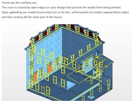
I sent a model of a building to ShapeWays for printing, and it failed the mesh check because of open edges (see attached). The yellow lines identify the offenders. The attached model includes a window and an interior block created to beef up the wall thickness for printing - both of which show up in yellow on the analysis. The interior block was an extruded polygon selection. And I suspect the windows were created with a similar process, then cloned for placement.
I did a mesh check but didn't get anything I recognized as an alert. So I'm not sure how I would go about finding/repairing this sort of thing in the future.
Thanks
-
Hi MFVis,
Please have a look here:

Perhaps find a good balance with Polygon reduction (e.g., 88%)
If you don't want to model it to get a single mesh, this would be my way to do it, and I have gotten a lot of great results in plastic and metal. I have never sent in more than one object (going by the Object Manager) to be printed. I'm currently not aware of their limits of model density. They need a single model and not an active Volume object.
To model this would mean first optimizing the window, especially the vast Glasblock, which needs attention. Then, pull the wall extension out of the window, which you can easily connect.
All the best
-
Yes, I considered using the volume builder, but I haven't had good luck with it for geometric objects in the past. However, your sample looks pretty sharp, so I will give it a study. It would greatly simplify the prep for printing on the modeling side (though it does take a while to process).
What does it mean for an object to have "open edges?" I optimized the extruded interior block but it didn't seem to make a difference in how it was handled. Unfortunately, mesh analysis has not been a strength of mine.
-
Thanks for the reply, MFVis,
Yes, Volume needs some exploration to find a good balance. The Mesher set to Adaptive between 0.5 and 5% (I used 3% in the example above) will help to keep things reasonable.
Open Edge Question: Upload only the "Window Casing Master" frame. You already have a clue. Exploration – Just take the vertical side polygon of it and pull it in one or the other direction. There is a lot of overlap of edges and geometry.
Here is my take on the frame, which was tested in Shapeways and found to be OK. The file you shared had 119 polygons; my version has 82. Can you see a difference? They look the same, but a huge difference in Polygons.
CV4_2024_drs_23_MOcm_01.c4d
All the best
-
Ha! Is there a command for removing the overlapping polygons and patching the gaps? The optimize command doesn't appear to do anything when I apply it. When I try Weld, everything goes nuts. Shooting in the dark.
-
Hi MFVis,
Yes, that would be great, a function that knows which one to delete.
The polygons inside the mesh are not double polygons; they are somewhere, and finding which one to keep is not easy for an algorithm.So, the first test for me is typically the Modeling Check; do it on a copy while hiding the original. It lets you see what the whole thing is about and lets you select the parts that will not work.
If you delete them, you might delete too much, but if you do it with a copy, it helps to understand the problem.Next is a simple one: place the object under a Subdivision Surface. It shows often where things went wrong.
With that knowledge, some polygons can be picked out pulled on to see if they are connected, etc. CMD-Z brings it back, then uses the selected and Selection> Hide Selected. With this, more can be seen inside of the object.
Now comes the hard part: repair or start over.
The answer was easy in this case: start over, but use a few polygons to be fast with it.
The front frame selected (visible only), Invert [U~I], then delete all others.
The remainder selected and Extrude with Create Caps on.
The offset can be measured from the original part.
Now: Create Caps OFF! This is often forgotten and creates models like the problem model we discuss. So, always OFF after an operation.Then offset some of the other parts (Symmetry selection can help here)
The lower part of the frame has a titled area, which can be easily moved with the related points. Extrude the small side as in the original. Done.
Check with SDS to see how that should have looked to gain an idea for future tasks.
All the best
-
Ah! Well that's a surprise. Cinema seems to have a magic checkbox for just about everything - I assumed something so basic as fixing sloppy modeling techniques would have been resolved long ago

When I started this project I was working fast and dirty - assuming all could be fixed in the print. Ha! Lesson learned. -
Thanks for the feedback, MFVis,
Well, that is pretty much why I started with the Volume Workflow.
The Remesh Object is perhaps one of the most helpful functions here, but even this option has no idea which one of the polygons to take here.
There are limitations, as one might want to keep the polygon while the next artist the other polygon. It is not that simple. If anyone has an idea, submit it to MAXON.
Have a great weekend.
