Ah, that makes perfect sense Dr. Sassi. I thought I saw that it was new, but it didn't quite register with me. Thank you for pointing that out. I will update, but when I'm done with my current project.
much appreciated,
Mike
Ah, that makes perfect sense Dr. Sassi. I thought I saw that it was new, but it didn't quite register with me. Thank you for pointing that out. I will update, but when I'm done with my current project.
much appreciated,
Mike
Thanks Dr. Sassi. i am in the middle of a project, but it will be worth updating. Just to confirm - are you saying that these additional parameters are only available in 2025.2.1?
I'm currently using 2025.1.3
Thank you for your quick reply, Dr. Sassi. I opened the file, and here are the parameters I am seeing in your file for the Look at Camera tag.
Hi. I'm trying to use the Look at Camera tag on some geometry in a group null. The problem is that when I put the tag on it, it gets flipped around 180 degrees in the viewport.
In the documentation, there is a checkbox called "invert," to flip it around so it faces the camera. The problem is that this and most other parameters aren't available in the tag properties in the attributes manager. The only one that does show up is a "change pitch rotation" checkbox. Am I doing something wrong?
thanks,
Mike
It was so awesome, I watched it twice, Dr. Sassi. Please tell him thank you very much for creating that video.
Mike
For future reference for anyone seeing this question, there's an excellent video on YouTube on this subject:
https://youtu.be/USzcXIfGmbQ?si=DE6w-90vOJ6oXgSD
[SOLVED] Dr. Sassi, I have found in the documentation under The Node Editor | Redshift Nodes | Redshift Utility Nodes | Surface Nodes | Contour:
"it is confined to the inner bounds of an object. Technically, a contour can never render outside of an object's silhouette but a workaround can be used to achieve a similar visual effect as described in the Contour Behavior section below, Breaking Boundaries." Essentially, I have to add a material with contours onto something in the background. The intersecting lines then render the "missing half" of the line because the lines are only rendered within the geometry. In my case, I put the Toon material on a ground plane, and it then rendered as I wanted it to look.
Thank you for replying, Dr. Sassi, I appreciate it. The image and render result are the same. Here's another example of two intersecting platonics. I have both the internal and external lines set to 10 in the contour node. As you can see, the internal lines are rendered doubly thick as the external lines. I'm not sure what's causing the disparity in thickness.
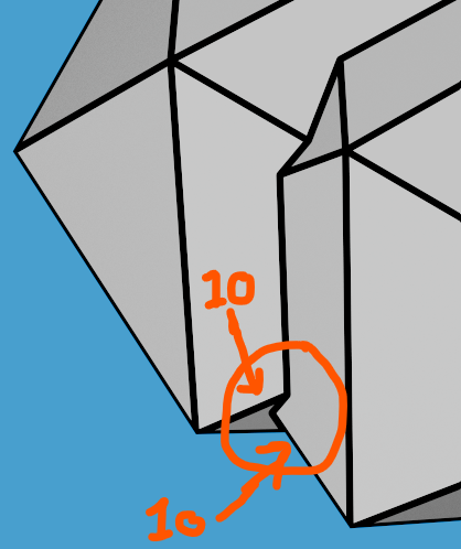
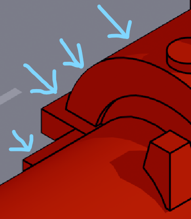
Hi. I'm seeing inconsistent line thickness between external and internal lines. I have them both set at thickness: 6 in the contour node but the external lines are thinner, as if they're drawn behind the geometry. Am I missing a setting?

Close Dr. Sassi, but not quite, and I appreciate your attempt! My winding colorful path is not part of the cloner. The cloner has one child (a cube), mode:Object, distribution: surface, and the surface object is a plane with some subdivision surfacing to make the plane look hilly. The clones begin to appear as a plain efffector's linear field sweeps over it, "growing" the cubes from a scale of -1 to 0. It seems like the variation shader in the winding path's material takes into account the sum total of all objects in the scene when it calculates the random seed. That's the only thing I can think of. I'm not keyframing anything int he variation shader itself, and the "flickering" of colors in the path only occur within the field's animation timespan.
I have a winding pathway (an editable cube with many polygons) with the variation shader set so each of its polygons have a different color. Along either side of this pathway, I'm growing cloned cubes by means of an animated linear field. The problem is that while the field animates (growing the cubes from scale -1 to 0), polygons in the pathway change colors as if its variation shader random seed has been keyframed, but it hasn't. Is there a way to prevent this?
thanks,
You're welcome Dr. Sassi. I didn't avoid the boole, I just made it larger to accomodate all of the clones. What I noticed was that clones were changing color, but only when another clone moved to within the previously smaller sized boole. My guess is that it was throwing off the clone indexs somehow.
Hi Dr. Sassi, thank you for your response, as always. You've been very helpful to me and I appreciate it. I think I solved this issue. The culprit is the Boole that the clones are sitting in. I have an array arranged as a grid, and the clones are spread out along the z-axis. All of the clones are then flattened down to the same z-position. When they're coming together, they're "trimmed" to within a volume in a Boole. What I noticed was that some of the clones originally reside outside of the Boole volume, so each time one of these clones entered into the Boole, that indexed clone color would change. I tested this without the clone being in a Boole and there wasn't any flickering. Problem solved. Thanks again!
Hi. I have a cloner with a material containing the variation shader in the color channel. This cloner has one cube as its child, and has two effectors: a Hide Selection and Random. In both effectors' Parameter tab, Color mode is set to off. In the Random effector's Effector tab, I am animating Maximum and Minimum to create movement. The problem is that these cubes are changing colors until the animation completes. I want each of these cloned cubes to maintain one steady color from start to finish. I am not sure what's causing this. Any help is greatly appreciated, thank you!