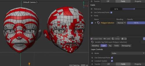
Hi, I am trying to transfer a polygon selection from one to another tag (same and different mesh with same topology) by using fields in the tag and drag the original selection in the field. Even when activating Index, the selection looks quite different.
R
Posts made by reading-card
-
Polygon selection tag transferposted in Question & Answers
-
RE: scene nodes questionposted in Question & Answers
found a solution by altering a scene node example
-
RE: scene nodes questionposted in Question & Answers
here is a semi-procedural scene that illustrates what I am trying to achieve.:
shrink node 01.c4dThe selection is shrunk and inverted manually in this case and I hope the scene node system is capable of providing procedural functions for that. If there is any tutorial or documentation, please let me know. I didn't find anything so far. AI is giving suggestions that are not supported by the current C4D version, maybe because selection strings could be used for those nodes in older versions and node names changed.
-
scene nodes questionposted in Question & Answers
Hi,
On a mesh with a polygon selection tag, I want to extrude the selection. I apply a Polygon Bevel node and add the selection name in its field (that works).
Then, I want to shrink the selection and apply another Polygon Bevel node extrusion to the shrinked selection (can't figure out how, as there is no selection string field in the Shrink Selection node.
Then, I want to delete all polygons that are not extruded. That might be possible with the delete node as it has a string field in combination with a invert selection node (which has no string field).
I am not sure if that's the functional benefit that some nodes have selection strings and others not. But from a usability point of view, it's quite confusing. Maybe there is a deeper logic it that I haven't discovered yet. Many thanks for any suggestion.
-
RE: Funky rigid bodiesposted in Question & Answers
Thanks for the scene. I do not expect 100% correct physics simulations, nor do I want to argue on that. However, the setup I tested illustrates huge deviations from what one would expect from a very simple simulation according to the basic principles of physics calculation. Considering the amount of parameters available in Maxon's physics, it is a quite alerting that even the simplest laws of physics are not reproducable.
It seems to be a common issue with recent C4D's releases that functions are not working as expected when applied differently than advertised in Maxon's tutorials and samples. That's a huge restriction for artists who are intended to use the software more creatively and lead to results that are rather driven by software developers than creativity. This contrasts the approach of functions such as MoGraph, where developers created robust, modular system, which provided a huge freedom for new creative applications even beyond the imagination of the developers. When I use C4D now, I spend 80% of my time on finding workarounds for bugs rather than creativity, which can be quite frustrating sometimes.
-
RE: Funky rigid bodiesposted in Question & Answers
...increasing the angular damping also helps a bit in combination with 100 substeps (maybe trajectory force shifts to rotational force). But after a few more seconds, the simulation gets random again, even without rotation.
-
RE: Funky rigid bodiesposted in Question & Answers
...when increasing the substeps, the simulation becomes more accurate for the first 2 seconds. But the viewport playback performance drops significantly.
scene:
maxon physics errors 03 (substeps 100).c4d -
Funky rigid bodiesposted in Question & Answers
Physics in C4D act very inconsistent when simulating with a linear array of clones (bouncing in random speeds and heights).
Scene attached:
maxon physics errors 03.c4dPS: I also got in touch with the maxon support but as they usually file a bug that takes years to fix, I am wondering if someone has a quick hint.
-
RE: Scene Nodes and Fields?posted in Question & Answers
Thanks for the Demo. The Plain deformer is reliable, but it doesn't extrude in terms of creating new edges and subdivisions. It's strange that scene nodes are not supporting fields in that context. I thought it is supposed to be modern, node based approach of Mograph's modular system, but seems less functional than the old MoExtrude and incompatible with fields. Thanks for checking! Really curious if there is a solution...
Btw, do you know if there is a more procedural Morph setup? At the moment, I need to exchange/bake the two meshes and reinitialize the morph tag every time I want to apply the effect to a different mesh topology or selection. I was trying to use Instances, so that I only need to change the source mesh once, but that doesn't seem to work either.
-
RE: Scene Nodes and Fields?posted in Question & Answers
Attached a test with a custom scene node to illustrate the approach. I had to duplicate the mesh and use morph (driven by a field) between the zero extruded and the 100% extruded mesh. Also, the extruded polygons appear quite messy. I am wondering if this can be achieved more elegantly.
-
RE: Scene Nodes and Fields?posted in Question & Answers
Thank you for the example.
I am looking for something similar to the Maxon training tip video above, where the field/vertex map influences the amount of extrusion for individual polygons. Eg, a noise field would extrude some of the selected polygons higher than others. Your example extrudes all selected polygons evenly depending on the distance of the field to the centre of the mesh. -
RE: Scene Nodes and Fields?posted in Question & Answers
A workaround would be morphing (controlled by a field) between the zero extruded and extruded object. However, I was hoping there is a more convenient solution...
-
Scene Nodes and Fields?posted in Question & Answers
Hi, I would like to achieve something like this: https://www.youtube.com/watch?v=vUT6Ps0nTP8
But I need to extrude complete polygon islands of a polygon selection tag rather than individual polygons. It's possible with the Bevel object. But I can't find a way to influence the size of extrusion by a vertex map or field. Was trying to use scene nodes but don't really understand its logic. There is no clear documentation and node names, structure, etc, seem to change in every version. So it's hard to figure out a solution, or evaluate whether it is even possible. Thanks for any hint!
-
RE: Cloth glitch on procedural meshposted in Question & Answers
Btw, C4D support confirmed it as bug.
-
RE: Cloth glitch on procedural meshposted in Question & Answers
Your example used rectangular shapes. The example I sent don't have rectangular edges. If you like to disprove, please use the same data. I know that the connect function only works in a certain range. Even considering C4D's frame delay difficulties, the mesh I sent is always connected. Add a smooth modifier and it will be always smooth. Any brakes in the mesh would lead to glitches in the smoothing (or just phong). So this is an welding bug that appears when using cloth (or maybe other features). Even Scene Nodes Like "Extrude" do not work correctly. The last reliable function was using "Py-ParametricTools". I guess that was back in 2016.
-
RE: Cloth glitch on procedural meshposted in Question & Answers
Thanks for the examples. I've informed the tech support as you suggested. Let's see if they have a solution.
When looking at the point IDs, there are sometimes two IDs overlapping each or IDs appear where there are no points. When baking the mesh with this wrong IDs, it seems all welded fine. It looks like a bug that screws up the underlying topology and although it's not visible at the first glance, it confuses the cloth sim. -
RE: Cloth glitch on procedural meshposted in Question & Answers
Thank you for your suggestion. I am looking for a none destructive, procedural solution as the face and the loft will change in future. In the original scene, the actual Moves by Maxon face mesh is used and will be replaced with further face captures. I just baked it to simply the scene. Also, the design of the loft extrusion needs to remain procedural during the creative process to test the behavior of different loft shapes along with the cloth simulating. Thus, the procedural welding is crucial.
I have tested the welding intensively by adding a Smooth Deformer and Subdivision Surface to the procedurally welded mesh. If points would not be welded or wrongly welded, it would cause already visible glitches, holes or or hard edges. So it seems the problem is somewhere else...
-
RE: Cloth glitch on procedural meshposted in Question & Answers
Thank you for the prompt reply.
Had a look at your scenes and both bypasses the essential part: procedurally connecting two (deformed/animated) meshes at their edge points who fit seamless together and add additional effects to it like cloth simulations. This approach preserve a valuable flexibility during the creation process and I am wondering if C4D is capable of that. While the points/UVs remain consistent, it seems the "Mesh-Chaos" is caused by hidden inconsistent mesh interpretations. Would be incredible useful to find a solution for that. -
RE: Cloth glitch on procedural meshposted in Question & Answers
sample scene download link: https://www.dropbox.com/scl/fi/n4ek69jut3s95gozt1ro2/Cloth-glitch-on-procedural-mesh-01.zip?rlkey=dadewn8jts9zydrteb4364j3o&dl=0
-
Cloth glitch on procedural meshposted in Question & Answers
Hi, I am trying to apply cloth to a procedural mesh. The mesh merges a face mesh from "Moves by Maxon" with a Loft. In order to let the loft's edge points have the same position as the face's edge points for a exact weld, I used a edge cloner or the "edge to spline" plugin. The points are welding correctly (a subdivision object or smoothing creates a smooth even mesh).
When applying a cloth tag, the mesh shows constant glitches. It seems like the mesh topology would constantly change. Maybe the procedural edge points causing a problem, although if it's point ID's would change, the loft and and welding would change too (not only the cloth simulation). I tried many approaches (using morph, scene nodes, etc.) Nothing works. Thanks for any suggestions!
I am also trying to attach a sample scene but the website states an error.
[Cloth glitch on procedural mesh 01.zip]error