Adding displacement to a mesh created from an extruded spline
-
I am having difficulty adding displacement to a mesh I created from an extruded spline. I have an RS material I've created that has a displacement map. I've turned on Geometry Override, Tessellation, and Displacement.
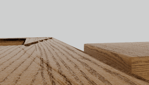
Turning on Tessellation and Displacement gives me distorted geometry, as seen on the left in the screenshot.
Another approach I've tried is to use Volume Builder/Mesher/Remesher to get better geometry, but I could never get a suitable result. The edges were always uneven.
Are there any other options to try or is there a better approach altogether?
Here is the project:
https://drive.google.com/drive/folders/1B_vW1mxtGR6jTfqV12RZPsBq1yC8ErbW?usp=sharing -
Hi kariomart,
Thank you very much for the model and for using Google Could services.
There are some problems with the model besides the Displacement being relatively high. (Perhaps another selection and the cutout area with less Displacement.)
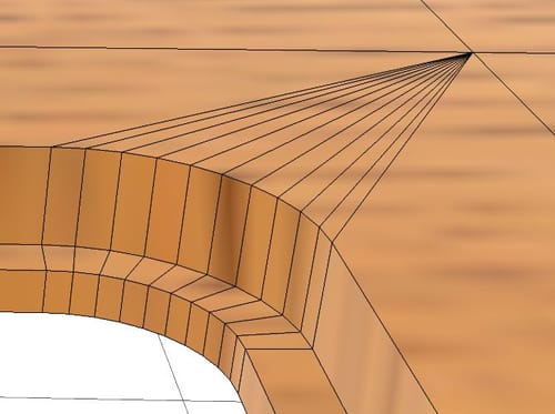
The easiest to spot problem is that the main area is an N-Gon. N-Gons are great during modeling; for rendering, those are a gamble. In other words, avoid them.
The other area where it is harder to quick fix is the cutout, a kind of model several times, with polygons in the same position and double, etc. I have left them in TOP.1, but I replaced that part completely in TOP.2
https://stcineversityprod02.blob.core.windows.net/$web/Cineversity_Forum_Support/2024_PROJECTS_DRS/20240205_CV4_2024_drs_24_RSgd_01.zip
Remodeled
Let me know if you need some guidance in remodeling.
All the best
-
@Dr-Sassi Hi Dr. Sassi,
Thank you so much for this, it's exactly what I was looking for. My technique for the cutout was inspired by a previous post you helped me with.And yes, I'm very interested to know how you remodeled everything, particularly the corners. As far as rendering, do triangles need to be avoided as well?
-
Hi kariomart,
In the post above I delete a lot and started over.
Here I start from scratch, please have a look:
https://stcineversityprod02.blob.core.windows.net/$web/Cineversity_Forum_Support/2024_Clips_DRS/20240207_board-holes.mp4Perhaps some more care is needed, to cut the larger polygons, to get a more equal flow. This is just a quick demo.
The file
CV4_2024_drs_24_MOho_01.c4d
With RS Render Object
CV4_2024_drs_24_MOho_11.c4d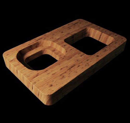
The two large holes created some challenges. Hence, I showcase those.
Are quads always needed that needed? Not really, as long as they are not very slim and long. However, if there is any kind of deformation or animation of the shape, avoid triangles. If you would like to use subsurface methods, quads are preferable. The best mesh is based on squares.When things deform a quad while turning into triangles during render time, there are two options in which a triangle can be produced. The one that creates the least obvious surface is typically used. But if that triangle pair is already determined, the deformation might look ugly if the "diagonal" edge defining the two triangles is working against instead of along the deformation.
I have attached the file and put some more time into it. But look if the little video already answers most of the questions.
I have not used Bevel here; I used Inset to define the edges.
Cheers
-
@Dr-Sassi Thank you so much for everything. It's taught me new and valuable techniques I'll continue to use. One last question: does the organization of the topology (straight rows and columns) or density matter when it comes to RS displacement, or is it just a matter of eliminating n-gons?
-
Hi kariomart.
N-Gons are great for modeling; after that, they should go.
With the Remesh Generator, we have a great and fast way to produce lovely meshes for a wider variety of objects. Is that always working? It depends. Trial and error from time to time, sure.
Anyway, please have a look here.
CV4_2024_drs_24_RSdp_11.c4dCompare the results when rendering the scene. The scale will change if you move the time slider; frame 30 is perhaps a good starting point. I think the object on the right will clearly show the minimum quality. It's the same material and the exact same RS Object Tag. Just the underlying polygon setup differs.
All the best