Dear Friends,
Some of you have followed my journey since I joined Cineversity on May 4, 2006, while others might remember me even further back from my years teaching Cinema 4D with Pixelcorps (PXC). Since 2004, along with four different versions of our forums here, plus the one from the Pixelcorps, I have had the privilege of answering around 30,000 questions. Whether through project files, images, or those quick one-minute screen captures, being there for you has been my constant.
I still vividly remember being a demo artist at NAB in 2006 when MoGraph was first premiered; sharing over a hundred videos shortly after to help everyone get started remains one of my favorite milestones.
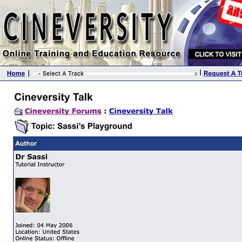
CV1 where is all started with Cineversity in 2006! Sometimes with 30 questions a day.
A lot has happened since those early days, but one thing has always been crystal clear: your creativity is boundless. I am so proud of the work you’ve done and the trust you placed in me—especially those of you who reached out with questions that felt difficult or uncomfortable to ask. I took that trust seriously and learned from every single one of those interactions. Your needs and your curiosity taught me more about this industry and our tools than I could have ever learned through any other source.
I have truly enjoyed being here for you pretty much 24/7, through holidays and vacations alike, because I love what I do. As things often do, life is changing. Structural changes allow me to face new challenges, and I hope I can grow into those. Those changes also require me, after 22 years of answering in various forums, to stop – for now. Something that pains me, and I feel the loss.
I want to say a sincere thank you to every artist I’ve had the joy of interacting with here. You are all wonderful, and I hope you never stop exploring. I certainly won’t. While it isn't clear yet where or how I will continue, my hope is to find a new place to support the artist community at one point again, as that has become such an essential part of my life. Thank you for making Cineversity such a great experience: 2006-2026. Thank you. I surely will miss you all.
Please treat my dear friend Noseman with the same care you have shown over the decades, as I hand over this precious forum. Thanks for your professionalism and trust over the decades.
Keep creating!
Dr. Sassi
") via Maxon via tech-support.
via Maxon via tech-support.