@Dr-Sassi - thank you! I am still tinkering in between projects as I am able. I will see if I can implement one of your dynamic "control" methods here, and see what happens!
Thanks again,
~MV
@Dr-Sassi - thank you! I am still tinkering in between projects as I am able. I will see if I can implement one of your dynamic "control" methods here, and see what happens!
Thanks again,
~MV
That's great! Ironically, I work in the secondary packaging industry, so endless loops is pretty much all I ever deal with
I have been told C4D is a "surface" modeler, while SolidWorks (as a CAD package) is a parametric "solids" modeler - near as I can tell, it seems to be the 3D equivalent to raster (C4D) vs vector (SW). I use Okino NuGraf to convert the .SLDASM files into .C4D files, but there is no going the other way.
So there is something about the pure mathematical/formulaic representation of the 3D object (without tessellation), which, in my uneducated opinion, is likely at the heart of how/why C4D constraints don't behave as precise/consistent as corresponding mates in SolidWorks.
I did try a quick test using the hinge object (since each joint only operates in one plane), and aside from some funny jittery behavior, it behaves well in terms of the joints respecting each other (of course, all it can do right now is just fall down and swing uselessly like a limp arm). I am just not sure how I can use the simulation engine to constrain the beginning of that "hinge chain" to a given point/orientation. Not sure if that is even possible, but that would be mimicking the CAD world of SolidWorks.
I hadn't looked into limits on the joints - I will need to try those as well!
Thanks again,
~MV
Blast! I was really hoping there was a silver bullet I was missing.
What you described (in terms of splitting the IK with a shared goal/base) is where my last attempts were left in a hot mess. I've gotten close ... but never quite right.
I wish I better understood how C4D differs from something like SolidWorks in this capacity, since I have successfully "mated" up the same robot in SolidWorks such that all the joints know how to orient themselves based on the position/orientation of the EOAT.
But I have not, for the life of me, been able to recreate that behavior within C4D ...
Thanks again for taking time to look at it!
~MV
Hi @Dr-Sassi - thanks for taking the time to look at the file!
I hope I am not missing something key in the rig you sent - from what I am seeing, it doesn't look like an approach like this (which I have indeed tried!) will quite get me to where I need to be in terms of accurate IK control of the entire robot arm.
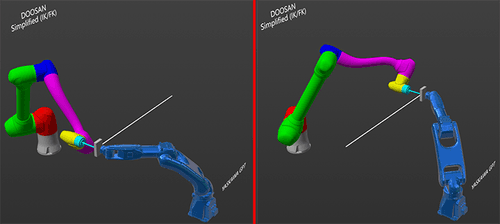
My end goal is to only have to animate the position of the mounting surface of the EOAT (end-of-arm-tool), such that I could draw a straight line without having to animate all the intermediate joints - this is the behavior for actually programming the robot, and I have seen this correctly/accurately "simulated" by a 3rd party robotic simulation software [Visual Components - https://academy.visualcomponents.com/lessons/doosan-robot-connectivity-plugin/ ]
Because all the joints have to coordinate in a non-linear fashion in order to drive the EOAT along a straight line (at any given angle within the working envelope), you'll never really be able to achieve that accurately by manually rotating the joints - even if you save some work by having J1/J2/J3 driven by IK.
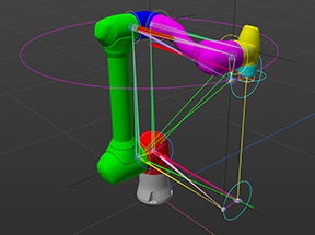
If you look at/click on the image below, hopefully it shows up big enough to illustrate what I am describing: the J4 (lavender) / J5 (yellow) / J6 (cyan) all have to coordinate their rotation if the EOAT is to maintain a locked orientation along a straight line. Even if I could get the positions dead on at either end of the move, the interpolated move in-between will not be along the straight line since a default spline within C4D is not the motion profile necessary on those joints to complete a linear move with the EOAT.
It seems to me that there is some kind of IK feedback loop which I am unable to replicate, because the IK-solution for J1/J2/J3 depends on the location of J4/J5/J6, but their orientation depends on the orientation of J1/J2/J3 ... so I have been chasing my tail! Part of my trouble is that I cannot seem to "push" anything with IK ... it is always a "follow-along" setup.
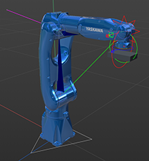
The blue robot is the YASKAWA GP7 I referenced earlier, which I did successfully rig up do this - I simply animated the position / rotation of the EOAT, and the intermediate 6-axes followed along beautifully based on IK and up constraints - but the catch is that here all the joints are in the same plane; the DOOSAN joints are all in slightly offset planes such that my method for the GP7 hasn't been working this time.
I hope that all makes sense! Again, thank you for taking the time to look at it. I can upload the file which is in the screenshot above, if that would be helpful - just send send me another Dropbox link.
Thanks!
~MV
Perfect - I just uploaded a file containing the original geometry (I did the color-coding, and attempt at organizing the joints/pivot points), as well as two of my half-baked attempts.
Thanks so much for taking the time to look at it!
~MV
Thanks for the quick reply, Dr. Sassi! Via work, we use OneDrive for file sharing - is that acceptable?
I would love to share some of my attempts - albeit they are all half-baked/messy and, obviously, not working!
~MV
Hello all,
I work as a concept animation-engineer in the industrial field, and am in need of a reliable rig for a DOOSAN H2017 6-Axis (degrees of freedom) robot:
https://www.doosanrobotics.com/en/product-solutions/product/h-series/h2017/
The DOOSAN has several unhelpful offsets from the base J1 rotation, making IK chains very difficult to manage - the J4 "forearm" rotation is particularly puzzling for me. I have tried pole vectors, various layers of experimental IK chains, constraints, and Xpresso all in an effort to get it to work:
My desired end goal is to be able to control the robot in a fully IK manner (i.e. only have to move/rotate the surface where you would mount your desired End-of-Arm-Tool [EOAT] ) I have actually been trying for the past year and half to figure out how to effectively use some combination of IK / Xpresso / Python, etc. to get this to work.
Does anyone have any tips or ideas how I might try tackling this differently? The solution continues to elude me. I am particularly wondering if their might be a method using dynamics/simulation methods (i.e. connectors/hinges), which I have not yet tried, which might be the ticket.
Thanks!
~MV
Sidenote: In the past, I was able to successfully rig a YASKAWA GP7, which was also 6-axis, via IK and up constraint tags ... but the axes are all in line on the YASKAWA. The fact that axes are offset on the DOOSAN has continually gotten my rigging efforts stuck.
https://www.yaskawa.com/products/robotics/robots-with-iec/articulated-robots/gp7
@Dr-Sassi - Good to know, thank you!
OFF TOPIC
Hello Dr-Sassi / MaverickMongoose - really appreciated this question/answer as it was exactly what I and my colleague were trying to figure out.
Can you offer any deeper insight as to what changed between R23 and 2025 (I know it is a big leap, but it took us a bit to decide to make the upgrade)? I know I did the approach MM mentioned regarding using a tracer on cloners with a collider body tag; there seems to be a quantum shift in how dynamics were calculated in R23 vs. the new simulation system in 2025, but I am not well-versed enough in the inner-workings to know why.
Previously, I could use the approach MM described, without the need for an intermediate matrix. Why is that intermediate step now needed in 2025?
Thanks so much for the info if you have time for a response!
~MV