Hmm.. Not super good news for me  C4D is a premium program in so many ways, I really didn't want to have to move away from it. I
I'll look into both your answers in more detail, I do really appreciate the responses.
Hmm.. Not super good news for me C4D is a premium program in so many ways, I really didn't want to have to move away from it. I
I'll look into both your answers in more detail, I do really appreciate the responses.
Hello guys, did you ever make any progress with this? I've just opened a similar question on this here: https://cineversity.forums.maxon.net/topic/2379/glb-gltf-export-issues-named-animation-tracks
But I can't use FBX without breaking materials... Glad of any advice.
Hello all,
I've been asked to produce some models in a web ready format, so that they can be uploaded to our web viewer in either GLB or glTF. Cinema 4D is the program I know and enjoy - I don't really have experience in any other 3D modelling programs, so I'm a bit tied to it.
I've been struggling with this for a while now. I had to recreate all my redshift materials as PBR materials, and after a lot of tweaking I've got this looking really good. I have spent weeks on this getting the workflow right - exporting the Cinema 4d model as a GLB model and optimising it, without losing textures or breaking the model.
Having got that perfected, I'm now trying the process on another model, and this model needs to have named animation tracks. But this seems to be unsupported?
After some research I found this post: https://cineversity.forums.maxon.net/topic/375/name-animations-glb/4 - and also a youtube tutorial which involves exporting to FBX and then converting to GLB. This method creates named animation tracks from the take system perfectly.... But it breaks all the materials I spent so long working on.
Is there anyway to export to GLB or glTF from C4D, with both materials and animation tracks intact, or do I need to start learning blender or something?
Thanks Dr. Sassi, that makes loads more sense now. I was thinking of it like a float in javascript, where it can literally only allow a floating point number. I can see now that float inputs can accept all different inputs - thanks for the clarification!
Thanks Dr. Sassi. The real inputs are just super useful for connecting any data type, whereas the float is fixed to be a float only - you can't link anything into it. I don't use the dev forum a lot - will have a look though.
Is this a bug do you think? wasn't sure whether to report it to maxon but not sure if theres any reason that real inputs aren't included?
Hey guys, just using Xpresso for some calculations, and after fiddling around with a ton of nodes, I chucked it all out and am recreating it in Python for simplicity!
So among other inputs, I want 3 inputs of type "Real" to input mixed values to my script. This is where it gets weird:
so it comes with two as standard, but you can't duplicate them, copy them or create them. (But you can delete them). I need 3 real inputs... how do I fix this?
Steps to reproduce: create a null, add an Xpresso tag, open it in the Xpresso editor and add a Python node. Check the default inputs - both "Real". Then try and create a new input - be interested to know if it's standard for everyone not to have a Real input option. I'm running C4d Version 2025.3.3
I'm having trouble getting the math modifier to work as expected, as per attached file. I simply want to make liquid particles go up or down based on their color.
This is what I've done:
I'm presuming that the R channel value of a solid red particle will be 255?
So as I understand it, this means the red particles would have their upwards velocity increased (every substep? - currently set to 20) according to this formula:
velocity = velocity + color.r * v
So we start off with zero velocity so I assume the formula looks like this:
substep 1:
velocity = 0 + 255*100  // final velocity is 25500 for Y axis

substep 2:
velocity = 25500 + 255 *100 // final velocity is 51000

etc
So the particles should shoot up out of sight right? But instead what happens is they float slowly up to the origin of the project and then settle down and stop moving in the centre of the project. Please can I get some help as to why?
The distance tweak works perfectly, thanks so much for your help!
Please help, I'm trying to build a simulated track, similar to the chain simulation in the Cinema 4D help menu.
I've got it all almost there but I'm getting a weird issue - when I play the simulation, a single link flies off into the distance, and it seems to break the connector. All the other links work fine and collide as expected.
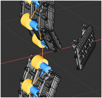
Here's my project:
Track Links v2.c4d
As you can see, I'm cloning the links onto a circle and so they should all be identical clones and positioning - I can't work out why this single link doesn't work! I've play around with the substeps, segments and interpolation of different objects, but there's no difference.
Thanks Dr. Sassi! That looks interesting, I'm going to be playing around with this today to see if I can get it to work on my scenes!